Series-fed microstrip array antenna for millimeter wave radar and system

A millimeter-wave radar and microstrip array technology, which is applied in specific array feeding systems, antennas, antenna arrays, etc., can solve the problems that cannot meet the requirements of the 94GHz frequency band of the millimeter-wave frequency band, the efficiency of the antenna array is not high, and the strong radiation loss of the feeder, etc. problem, to achieve the effect of low loss, small size, and small radiation loss

Inactive Publication Date: 2019-10-08
CHINA ELECTRONIC TECH GRP CORP NO 38 RES INST
View PDF11 Cites 7 Cited by
  • Summary
  • Abstract
  • Description
  • Claims
  • Application Information

AI Technical Summary

Problems solved by technology

[0004] Conventional microstrip antennas have a narrow frequency band, which cannot meet the requirements of the 94GHz frequency band in the millimeter wave band, and the feeder has strong radiation loss, resulting in low efficiency of the entire antenna array

Method used


Image

  • Series-fed microstrip array antenna for millimeter wave radar and system
  • Series-fed microstrip array antenna for millimeter wave radar and system
  • Series-fed microstrip array antenna for millimeter wave radar and system

Examples


Embodiment Construction

[0022] The embodiments of the present invention will be described in detail below. This embodiment is implemented on the premise of the technical solution of the present invention. Detailed implementation modes and specific operation procedures are given, but the protection scope of the present invention is not limited to the following implementations. example.

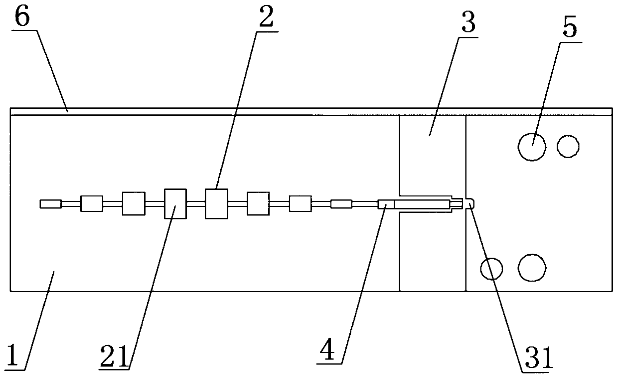
[0023] Such as figure 1 As shown, figure 1 It is a schematic diagram of the overall structure of the present invention. This embodiment provides a technical solution: a series-fed microstrip array antenna for millimeter wave radar. The present invention includes a dielectric plate 1, an impedance converter 4 for changing the edge impedance of the antenna , The coplanar waveguide 3 and the patch array antenna used to feed the antenna, the coplanar waveguide 3 and the patch array antenna 2 are both attached to one side surface of the dielectric plate 1, the patch The array antenna 2 is located on one side of the coplanar w...


PUM

PropertyMeasurementUnit
Thicknessaaaaaaaaaa

Abstract

The invention discloses a series-fed microstrip array antenna for millimeter wave radar, and belongs to the technical field of microstrip antennas. The series-fed microstrip array antenna comprises adielectric plate, an impedance converter used for changing the impedance of the edge of the antenna, a coplanar waveguide used for feeding the antenna and a patch array antenna, wherein the coplanar waveguide and the patch array antenna are attached to one side surface of the dielectric plate, and the distance between two adjacent microstrip patches ranges between one half and three quarters of the wavelength. According to the invention, the microstrip patches are mutually connected by adopting a series feeding mode, so that the antenna is enabled to be smaller in overall volume and lower in loss; and the feed network fed by the coplanar waveguide is adopted, the feed network enables the electromagnetic field to be mainly concentrated between transmission wires, the transmission performance is not affected by the distance between a conduction band on the antenna and a grounding plate on the substrate, the radiation loss is extremely small, the feed network is simplified, and the efficiency of the whole feed network is improved.

Description

Technical field [0001] The invention relates to the technical field of microstrip antennas, in particular to a series-fed microstrip array antenna for millimeter wave radar. Background technique [0002] 5G technology, the fifth-generation mobile communication technology, is a new generation of mobile communication technology for mobile communication networks after 2020. It will have ultra-high spectrum utilization and extremely fast transmission rates, which is an increase compared to 4G mobile communication technology. Class or higher, the rate can reach 10GB / S, and it needs to be able to meet the development needs of mobile Internet traffic increasing 1,000 times in the next 10 years. At present, low-frequency spectrum resources are very crowded, and it is difficult to meet the needs of future 5G communications. Opening up new frequency bands has become an inevitable choice for 5G, and millimeter waves have unique properties such as rich spectrum resources, good directivity, a...

Claims


Application Information

Patent Timeline
IPC IPC(8): H01Q1/38H01Q1/50H01Q21/00
CPCH01Q1/38H01Q1/50H01Q21/00H01Q21/0006
Inventor 曹锐李庄荣大伟姜力晖陶小辉
Owner CHINA ELECTRONIC TECH GRP CORP NO 38 RES INST
Why Eureka
Try Eureka