glass plate structure
A glass plate and structure technology, applied in glass/slag layered products, diaphragm structures, sensors, etc., can solve the problems of sound deterioration, resonance mode, residual reverberation sound, etc., to suppress the generation of abnormal sound, ensure Excellent strength and reproducibility
- Summary
- Abstract
- Description
- Claims
- Application Information
AI Technical Summary
Problems solved by technology
Method used
Image
Examples
Embodiment 1
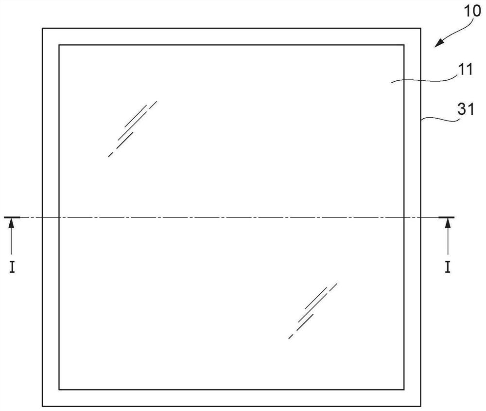
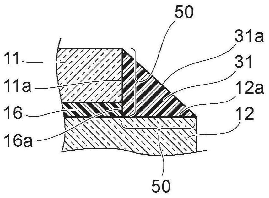
[0178] A glass plate A of 110 mm x 110 mm x 0.5 mm was prepared as the second plate, and the second plate was a substrate one, on which a glass plate with a viscosity coefficient of 3000 mPa·s was coated using a dispenser (manufactured by Musashi Engineering; SHOTMASTER 400DS-s). Silicone oil (manufactured by Shin-Etsu Chemical Co., Ltd.; KF-96) was used as the liquid layer. Furthermore, a glass plate B of 100 mm x 100 mm x 0.5 mm was attached to the center of the glass plate A as the first plate. Thereby, the glass laminated body arrange|positioned so that the position of all the end surfaces of the said 2 glass plates may not correspond was obtained. Next, apply UV curable resin (manufactured by Kyoritsu Chemical; XVL-14) on the level difference between glass plate A and glass plate B, and let it cure, and then make glass plate A a size of 103mm x 103mm x 0.5mm The unbonded part was cut in the same way, and the glass plate structure with the height difference sealing was ob...
Embodiment 2
[0182] A glass plate structure was obtained in the same manner as in Example 1 except that the glass plate A was changed to an acrylic resin substrate of 110 mm×110 mm×0.5 mm.
Embodiment 3
[0184] A glass plate A of 100mm×100mm×0.5mm was prepared, and the viscosity coefficient was uniformly applied on it with a dispenser (manufactured by Musashi Engineering Co., Ltd.; SHOTMASTER 400DS-s) with a gap of 5mm in width from the end. 3000 mPa·s silicone oil (manufactured by Shin-Etsu Chemical Co., Ltd.; KF-96) was used as the liquid layer. Furthermore, a UV curable resin (manufactured by Kyoritsu Chemical; XVL-14) was coated on the end of the glass plate A with a line width of about 2 mm. Next, a glass plate B of 100 mm x 100 mm x 0.5 mm was pasted as the first plate in a state deviated from the central part of the glass plate A by 1 mm in the up, down, and left and right directions, and the first plate was the substrate 2, so that the liquid thickness was Bonding was performed under reduced pressure with a thickness of 3 μm. Thereby, the glass laminated body arrange|positioned so that the position of all the end surfaces of the said 2 glass plates may not correspond ...
PUM
| Property | Measurement | Unit |
|---|---|---|
| viscosity | aaaaa | aaaaa |
| surface tension | aaaaa | aaaaa |
| thickness | aaaaa | aaaaa |
Abstract
Description
Claims
Application Information
 - R&D
- Intellectual Property
- Life Sciences
- Materials
- Tech Scout
- Unparalleled Data Quality
- Higher Quality Content
- 60% Fewer Hallucinations
Browse by: Latest US Patents, China's latest patents, Technical Efficacy Thesaurus, Application Domain, Technology Topic, Popular Technical Reports.
© 2025 PatSnap. All rights reserved.Legal|Privacy policy|Modern Slavery Act Transparency Statement|Sitemap|About US| Contact US: help@patsnap.com


