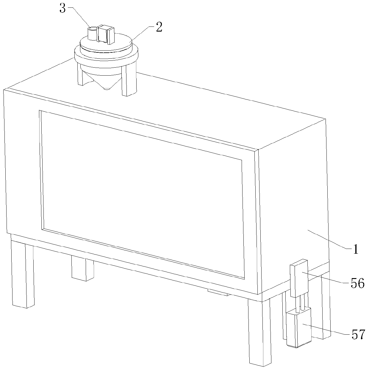
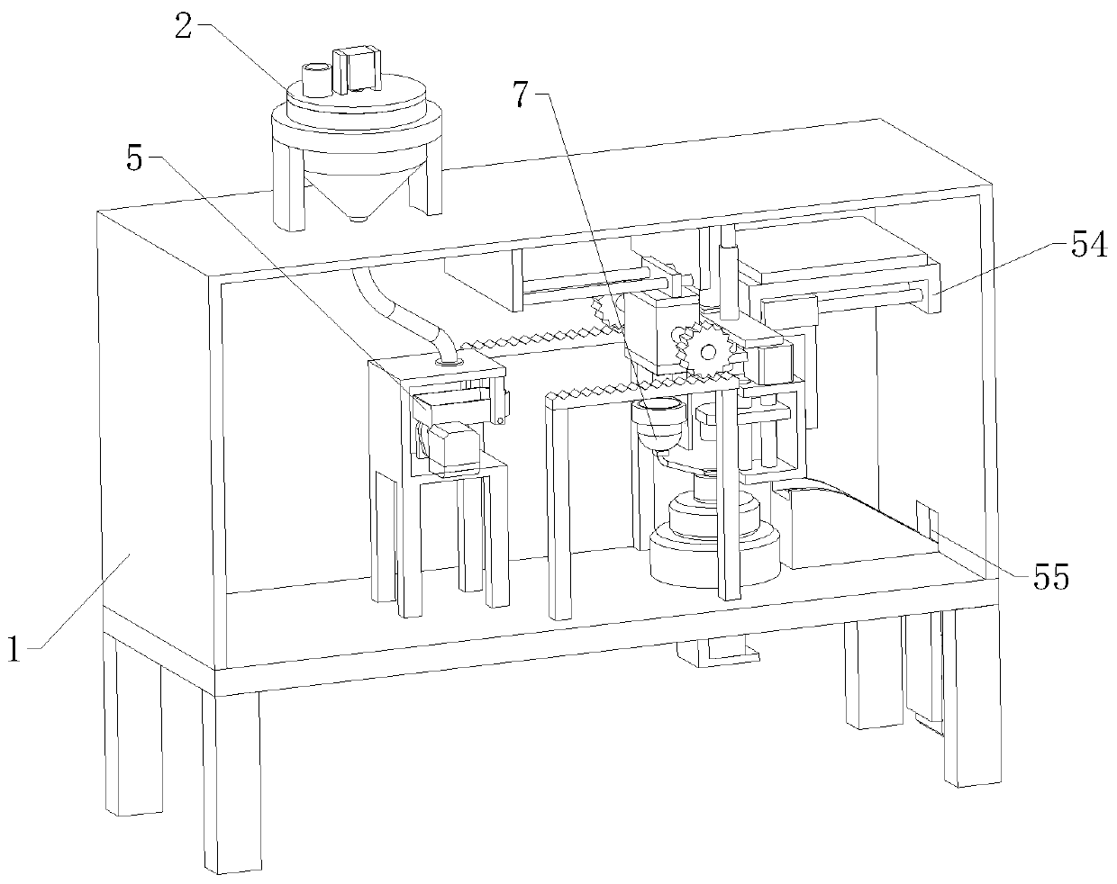
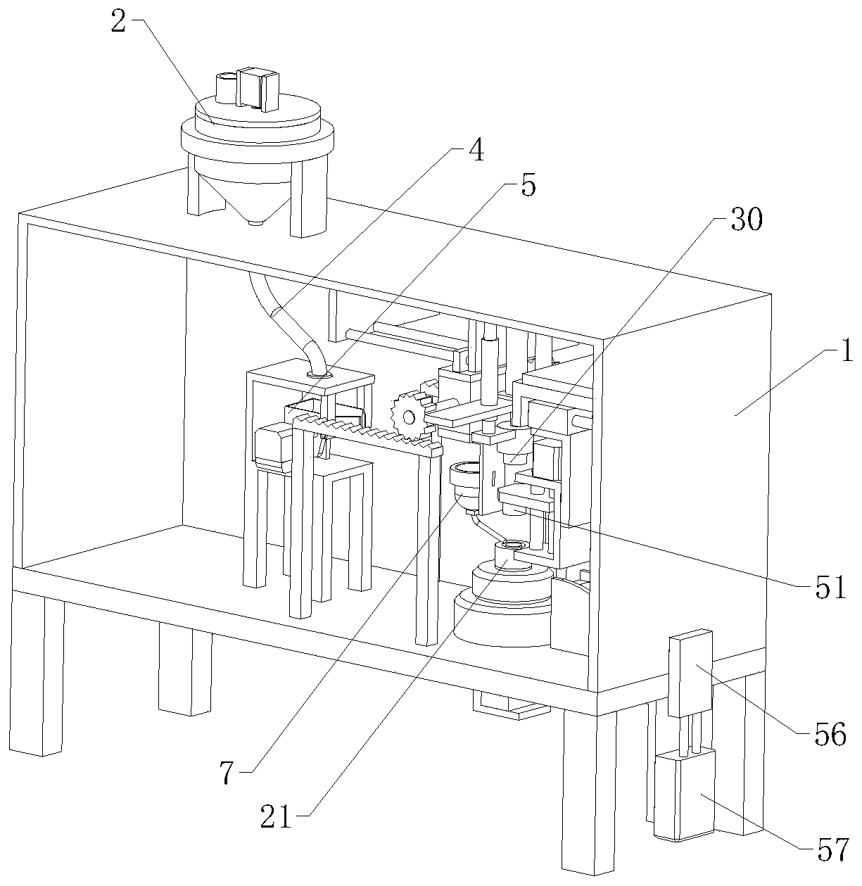
Automatic ring forming equipment of neodymium iron boron

A molding equipment, NdFeB technology, applied in the manufacture of inductors/transformers/magnets, electrical components, circuits, etc., can solve problems such as large output signal fluctuations, large magnetic pole fluctuations, and poor temperature characteristics

Active Publication Date: 2019-10-11
COLLEGE OF APPLIED SCI JIANGXI UNIV OF SCI & TECH
View PDF8 Cites 2 Cited by
  • Summary
  • Abstract
  • Description
  • Claims
  • Application Information

AI Technical Summary

Problems solved by technology

Surface chemical passivation is one of the good solutions. As a kind of rare earth permanent magnet material, NdFeB has extremely high magnetic energy product and coercive force. At the same time, the advantages of high energy density make NdFeB permanent magnet materials in modern It has been widely used in industry and electronic technology, so that the miniaturization, light weight and thinning of instruments and meters, electroacoustic motors, magnetic separation and magnetization and other equipment are possible. The advantages of NdFeB are high cost performance and good mechanical properties. The disadvantage is that the working temperature is low, the temperature characteristics are poor, and it is easy to pulverize and corrode. It must be improved by adjusting its chemical composition and adopting surface treatment methods to meet the requirements of practical applications. NdFeB magnetic materials, as rare earth The latest result of the development of permanent magnet materials is called "Magnetic King" because of its excellent magnetic properties. NdFeB magnetic materials are alloys of praseodymium neodymium metal, boron iron, etc., also known as magnetic steel, permanent magnet servo motors have high efficiency , low power consumption, high speed stability, reliable start, etc., among which the permanent magnet ring is the core component that determines the performance index of the servo motor. At present, domestic permanent magnet servo motors generally use NdFeB multi Pole permanent magnet ring, this kind of permanent magnet ring has the disadvantages that the geometric center does not coincide with the magnetic field center, the surface magnetic distribution is uneven (serrated), and the performance of each magnetic tile is different, which will cause large fluctuations in magnetic poles and large fluctuations in output signals. The technical defect will cause a lot of waste of raw materials and double the processing cost. The common solution is to use adhesive to connect the magnetic steel and the body. At this time, the strength and life of the adhesive severely limit the use of the motor. It is also difficult to precisely control the lifespan and the thickness of the adhesive, which directly affects the gap between the stator and the rotor of the motor, which reduces the efficiency of the motor to a certain extent. When making NdFeB radiation rings, it is processed through multiple procedures. It is necessary to hydraulically operate the NdFeB to press it into a ring shape, but generally it is necessary to manually load and unload the NdFeB material during the feeding process, and the NdFeB material needs to be weighed to put an appropriate amount of NdFeB The material is manually put into the lower pressure film tool, followed by hydroforming, and then the material is taken out manually, which is time-consuming and labor-intensive, which affects production efficiency. Therefore, we propose an automatic ring forming equipment for NdFeB, so that to solve the above-mentioned problems

Method used


Image

  • Automatic ring forming equipment of neodymium iron boron
  • Automatic ring forming equipment of neodymium iron boron
  • Automatic ring forming equipment of neodymium iron boron

Examples


Embodiment Construction

[0028] The technical solutions of the present invention will be further described below in conjunction with the accompanying drawings and through specific implementation methods.

[0029] Wherein, the accompanying drawings are only for illustrative purposes, showing only schematic diagrams, rather than physical drawings, and should not be construed as limitations on this patent; in order to better illustrate the embodiments of the present invention, some parts of the accompanying drawings will be omitted, Enlargement or reduction does not represent the size of the actual product; for those skilled in the art, it is understandable that certain known structures and their descriptions in the drawings may be omitted.

[0030] In the drawings of the embodiments of the present invention, the same or similar symbols correspond to the same or similar components; , "inner", "outer" and other indicated orientations or positional relationships are based on the orientations or positional ...


PUM


Abstract

The invention relates to the field of processing of neodymium iron boron magnets, and in particular relates to automatic ring forming equipment of neodymium iron boron. The automatic ring forming equipment of neodymium iron boron comprises a chassis and further comprises a feeding mechanism, a weighing mechanism, a horizontal material moving mechanism, a hydraulic mechanism and a blanking mechanism; the feeding mechanism comprises a stirring tank; the stirring tank is vertically arranged at one end of the top of the chassis; a feeding hole is formed on the top of the stirring tank; a materialguide pipe is arranged at the bottom of the stirring tank; the weighing mechanism comprises a weighing guide component; the weighing guide component comprises a weighing temporary storage box; a material guide hole is arranged at one end of the weighing temporary storage box; the hydraulic mechanism comprises an upper mould component and a lower mould component; the horizontal material moving mechanism comprises a horizontal moving component and a feeding tank; the blanking mechanism comprises a material fetching component, a horizontal blanking mobile component and a blanking track; the horizontal blanking component is arranged at one side of the upper mould component; the material fetching component is positioned below the horizontal blanking component; and the blanking track is positioned below the material fetching component. By means of the automatic ring forming equipment of neodymium iron boron in the invention, automatic pressing and forming can be realized; furthermore, automatic feeding and blanking can be realized; and the production efficiency is increased.

Description

technical field [0001] The invention relates to the field of NdFeB magnet processing, in particular to an automatic ring forming equipment for NdFeB magnets. Background technique [0002] Neodymium iron boron, simply speaking, is a kind of magnet. The difference from the magnets we usually see is that it is called the "magnet king" because of its excellent magnetic properties. Ndfeb contains a large amount of rare earth element neodymium, and Iron and boron are hard and brittle. Since the surface is easily oxidized and corroded, NdFeB must be surface-coated. Surface chemical passivation is one of the good solutions. As a kind of rare earth permanent magnet material, NdFeB has extremely high magnetic energy product and coercive force. At the same time, the advantages of high energy density make NdFeB permanent magnet materials in modern It has been widely used in industry and electronic technology, so that the miniaturization, light weight and thinning of instruments and met...

Claims


Application Information

Patent Timeline
IPC IPC(8): H01F41/02
CPCH01F41/0266
Inventor 孙康邱小童
Owner COLLEGE OF APPLIED SCI JIANGXI UNIV OF SCI & TECH
Why Eureka
Try Eureka