


Quick Research
Generate reliable direction feasibility study reports for your R&D in just a few steps.

Technical Q&A
Discover and master advanced knowledge NOW. Basics, ideas, possibilities, all at once.

Find Solutions
As an expert in R&D theories, this can generate solutions to your technical problems instantly.

Evaluate Feasibility
Analyze your overall solution with one click, know your potential R&D risks in advance.

Monitor Landscape
Get weekly tech updates, stay abreast of the latest tech innovations and key insights.
Desulfurized flue gas aftertreatment device and method and wet desulphurization system
A post-processing device and wet desulfurization technology, applied in the direction of gas treatment, separation methods, chemical instruments and methods, etc., can solve the problem of low heat and mass transfer efficiency between flue gas and cooling water, cooling efficiency needs to be improved, and large cooling equipment and other problems, to achieve the effect of prolonging the cooling time, reducing the heating range and improving the cooling efficiency
- Summary
- Abstract
- Description
- Claims
- Application Information
AI Technical Summary
Problems solved by technology
Method used
Image

Examples
Embodiment 1
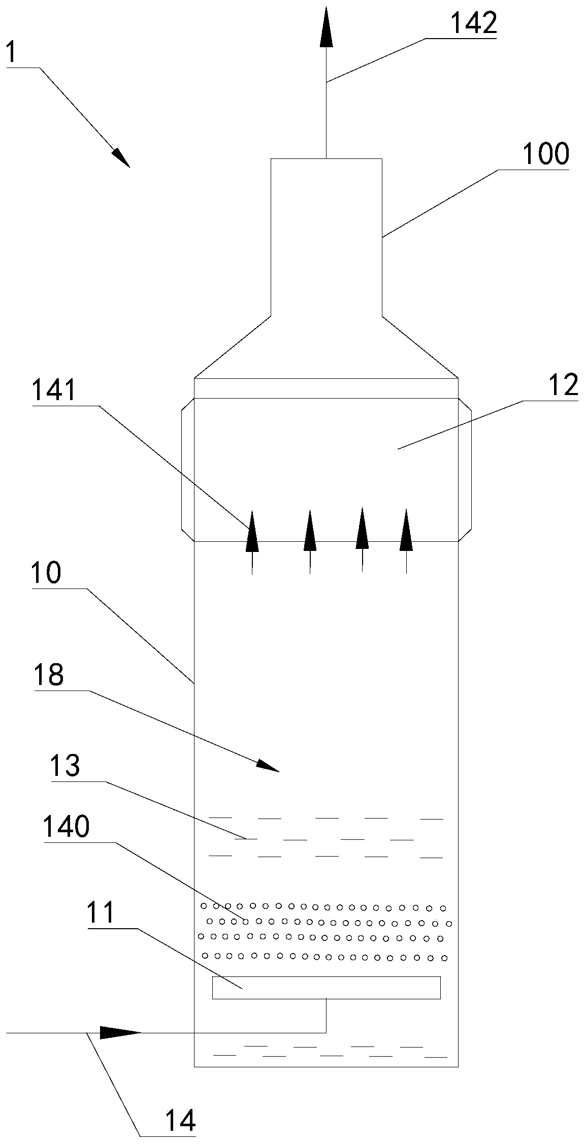
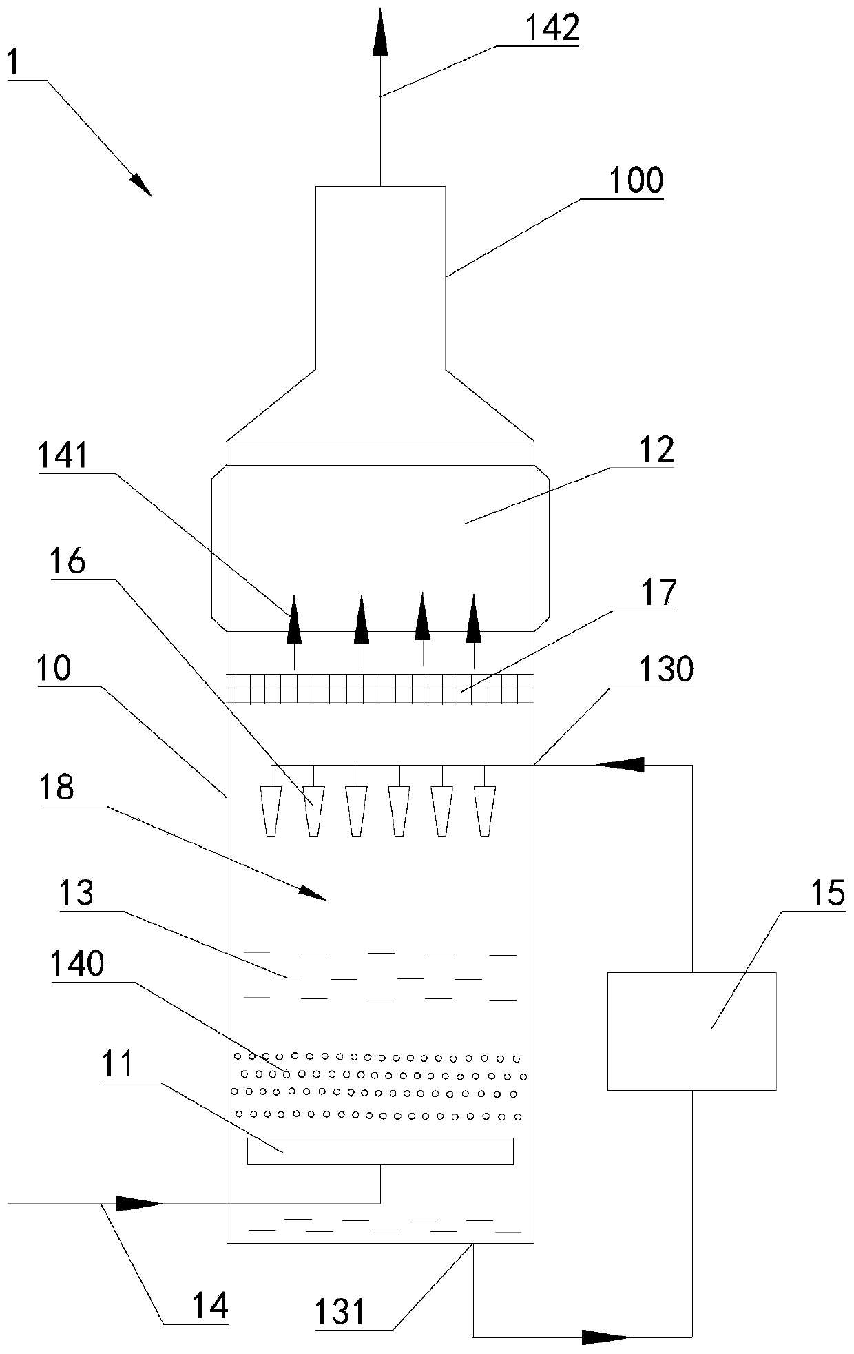
[0042] see figure 1 and figure 2 As shown, this embodiment provides a desulfurization flue gas post-processing device; figure 1 The first structural schematic diagram of the desulfurization flue gas post-processing device provided in this embodiment; figure 2 It is a schematic diagram of the second structure of the desulfurization flue gas post-processing device provided in this embodiment.
[0043] The post-processing device for desulfurized flue gas provided in this embodiment is used to perform further anti-pollution treatment on the flue gas that has undergone desulfurization treatment, especially to perform further anti-pollution treatment on the flue gas that has undergone wet desulfurization treatment.
[0044] see figure 1 and figure 2 and combine image 3 and Figure 4 As shown, the desulfurization flue gas post-treatment device 1 includes a treatment tower 10, a bubble generating assembly 11 and a heater 12. The bottom of the treatment tower 10 is provided wit...
Embodiment 2
[0065] Embodiment 2 provides a wet desulfurization system. This embodiment includes the desulfurization flue gas post-processing device provided in Embodiment 1. The technical features of the desulfurization flue gas post-processing device disclosed in Embodiment 1 are also applicable to this embodiment. Embodiment 1 The technical features of the disclosed desulfurization flue gas post-processing device will not be described repeatedly.
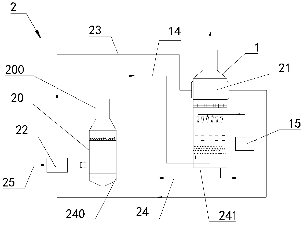
[0066] image 3 Schematic diagram of the structure of the wet desulfurization system provided in this example.
[0067] combine figure 1 and figure 2 and see image 3 and Figure 4 As shown, the wet desulfurization system 2 provided in this embodiment includes a desulfurization device 20 and a desulfurization flue gas post-treatment device 1 ; the exhaust port 200 of the desulfurization device 20 is connected to the bubble generating assembly 11 of the desulfurization flue gas post-treatment device 1 . That is to say, the desulfurized f...
PUM
| Property | Measurement | Unit |
|---|---|---|
| Diameter | aaaaa | aaaaa |
Abstract
Description
Claims
Application Information
 - R&D Engineer
- R&D Manager
- IP Professional
- Industry Leading Data Capabilities
- Powerful AI technology
- Patent DNA Extraction
Browse by: Latest US Patents, China's latest patents, Technical Efficacy Thesaurus, Application Domain, Technology Topic, Popular Technical Reports.
© 2024 PatSnap. All rights reserved.Legal|Privacy policy|Modern Slavery Act Transparency Statement|Sitemap|About US| Contact US: help@patsnap.com