Eureka AIR delivers breakthrough ideas for toughest innovation challenges, trusted by R&D personnel around the world.

Waste gas treatment device for paper mill

A waste gas treatment device and paper mill technology, applied in gas treatment, air quality improvement, membrane technology, etc., can solve the problems of sewage odor, atmospheric environment and human health impact, living troubles of surrounding residents, etc., to solve the problem of odor Effect

Pending Publication Date: 2019-10-15
WUXI LONGCHEN GREENTECH CO LTD
View PDF0 Cites 0 Cited by
  • Summary
  • Abstract
  • Description
  • Claims
  • Application Information

AI Technical Summary

Problems solved by technology

[0002] With the vigorous development of the paper industry, the problem of waste gas produced in the production process has gradually attracted people's attention. Pulping and papermaking is a chemical production process in which plant fibers are used as raw materials, and various reactions in the process will release a variety of waste gases; On the other hand, waste water from paper mills is recycled, and a large amount of organic matter is precipitated and fermented, causing foul smell in the waste water; therefore, while obtaining cardboard, it also emits a large amount of waste gas and other polluting gases into the environment. Effective treatment will have varying degrees of impact on the atmospheric environment and human health
[0003] In the prior art, the waste gas produced in the sludge room, sludge thickening tank, pre-acidification tank and anaerobic sludge tank in the papermaking process is discharged through a 15-meter exhaust pipe after being treated by an alkali washing tower. This method can realize the preliminary treatment of waste gas, which can basically meet the emission standards, but there is still a small amount of peculiar smell that is inevitable, which brings troubles to the lives of surrounding residents.

Method used


Image

  • Waste gas treatment device for paper mill
  • Waste gas treatment device for paper mill

Examples


Embodiment

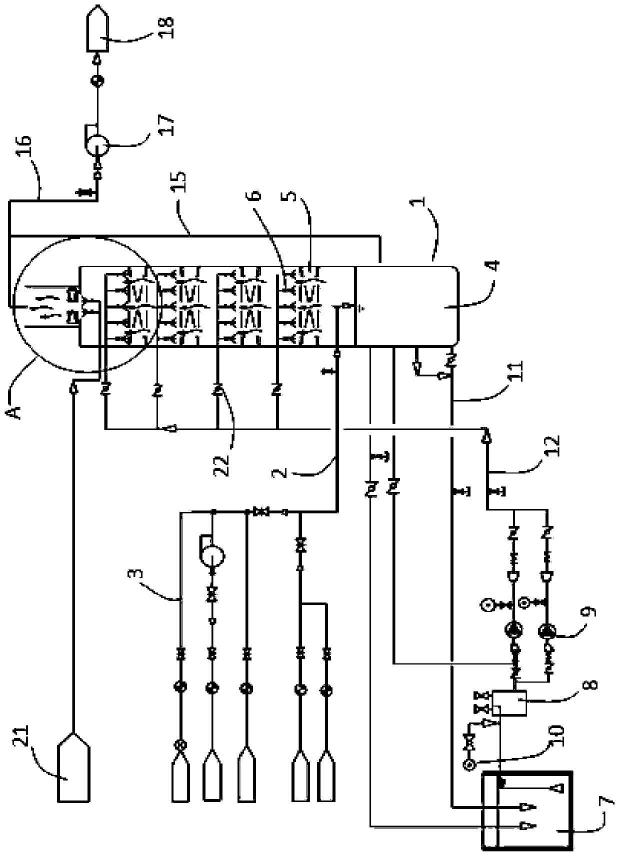
[0018] like figure 1 As shown, a waste gas treatment device for a paper mill includes a biological scrubber 1, one side of the biological scrubber 1 is provided with a waste gas transmission main pipe 2, and one end of the waste gas transmission main pipe 2 is connected to the biological scrubber 1, and the waste gas transmission main pipe 2 The other end is connected to several waste gas transmission single pipes 3 for collecting waste gas. The waste gas is generated from the pre-acidification tank, regulating tank, sludge thickening tank, primary sedimentation tank, etc. during the papermaking process. Each waste gas transmission A gate valve is provided on the single pipe 3 to regulate the internal exhaust gas transmission.

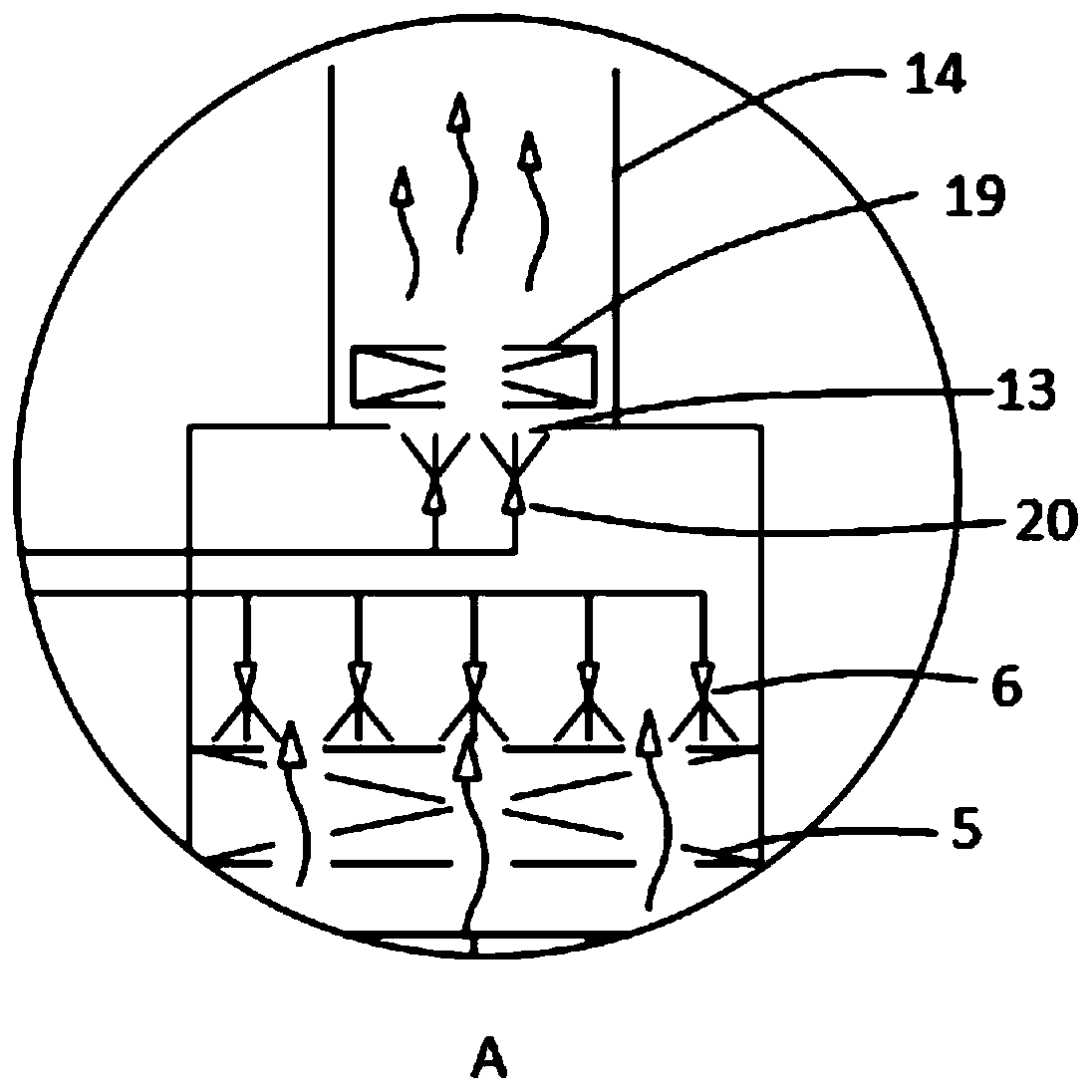
[0019] like figure 1 As shown, the biological scrubber 1 includes a liquid storage chamber 4 for holding circulating liquid, and above the liquid storage chamber 4, there are four levels of biological packing layers 5 equidistantly arranged, and above...


PUM


Abstract

The invention discloses a waste gas treatment device for a paper mill. The device comprises a biological washing tower, a waste gas transmission main tube is arranged at one side of the biological washing tower, the other end of the waste gas transmission main tube is communicated to a plurality of waste gas transmission single tubes, the biological washing tower comprises a liquid storage chamber, four-stage bio-filler layer and spray layers, every spray layer is communicated to an aerobic biological aeration tank, a water diversion tank and a spray pump are arranged between the aerobic biological aeration tank and the biological washing tower, a circulation discharge tube and a circulation return tube are communicated between the liquid storage chamber and the aerobic biological aerationtank, the circulation return tube is communicated to every spray layer respectively, a gas discharge port and a draining tube are arranged above the biological washing tower, and one end of the drainage tube is communicated to the aerobic biological aeration tank and an electric heating boiler. The waste gas treatment device for the paper mill can completely treat the pollution of waste gas discharged from the papermaking process to the atmospheric environment and completely solve the problem of odor.

Description

technical field [0001] The invention relates to the technical field of environmental protection, in particular to a waste gas treatment device for paper mills. Background technique [0002] With the vigorous development of the paper industry, the problem of waste gas produced in the production process has gradually attracted people's attention. Pulping and papermaking is a chemical production process in which plant fibers are used as raw materials, and various reactions in the process will release a variety of waste gases; On the other hand, waste water from paper mills is recycled, and a large amount of organic matter is precipitated and fermented, causing foul smell in the waste water; therefore, while obtaining cardboard, it also emits a large amount of waste gas and other polluting gases into the environment. Effective treatment will have varying degrees of impact on the atmospheric environment and human health. [0003] In the prior art, the waste gas produced in the s...

Claims


Application Information

Patent Timeline
IPC IPC(8): B01D53/84
CPCB01D53/84B01D2258/02B01D2251/95Y02A50/20
Inventor 薛宁苏仁伟韩建时
Owner WUXI LONGCHEN GREENTECH CO LTD
Why Eureka
Eureka Blog
Learn More