
Processing method for grinding circular ring end surface through grinding rod with large slenderness ratio and weak rigidity

A technology with large length-to-diameter ratio and weak rigidity, which is applied in the direction of machine tools suitable for grinding workpiece planes, parts of grinding machine tools, and grinding drive devices, etc. Safety accidents, poor system stability and other problems, to achieve the effect of precise and efficient automatic grinding, easy automation, guaranteed performance and life

Active Publication Date: 2019-10-15
DALIAN UNIV OF TECH
View PDF4 Cites 0 Cited by
  • Summary
  • Abstract
  • Description
  • Claims
  • Application Information

AI Technical Summary

Problems solved by technology

[0005] Aiming at the problems of low processing efficiency, serious grinding wheel wear, poor system stability and prone to safety accidents mentioned above, the present invention researches and invents a processing method for grinding the end face of a circular ring with a large length-to-diameter ratio and a weak rigid grinding rod.

Method used


Image

  • Processing method for grinding circular ring end surface through grinding rod with large slenderness ratio and weak rigidity
  • Processing method for grinding circular ring end surface through grinding rod with large slenderness ratio and weak rigidity
  • Processing method for grinding circular ring end surface through grinding rod with large slenderness ratio and weak rigidity

Examples


Embodiment 1

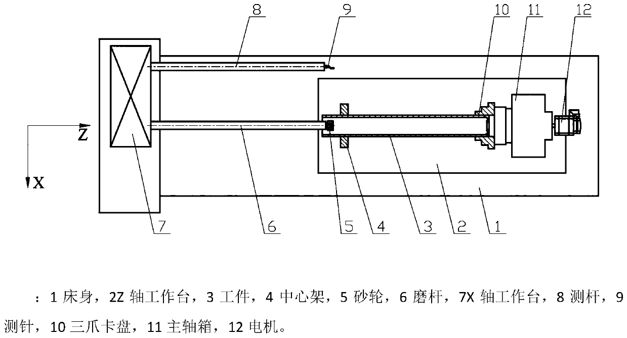
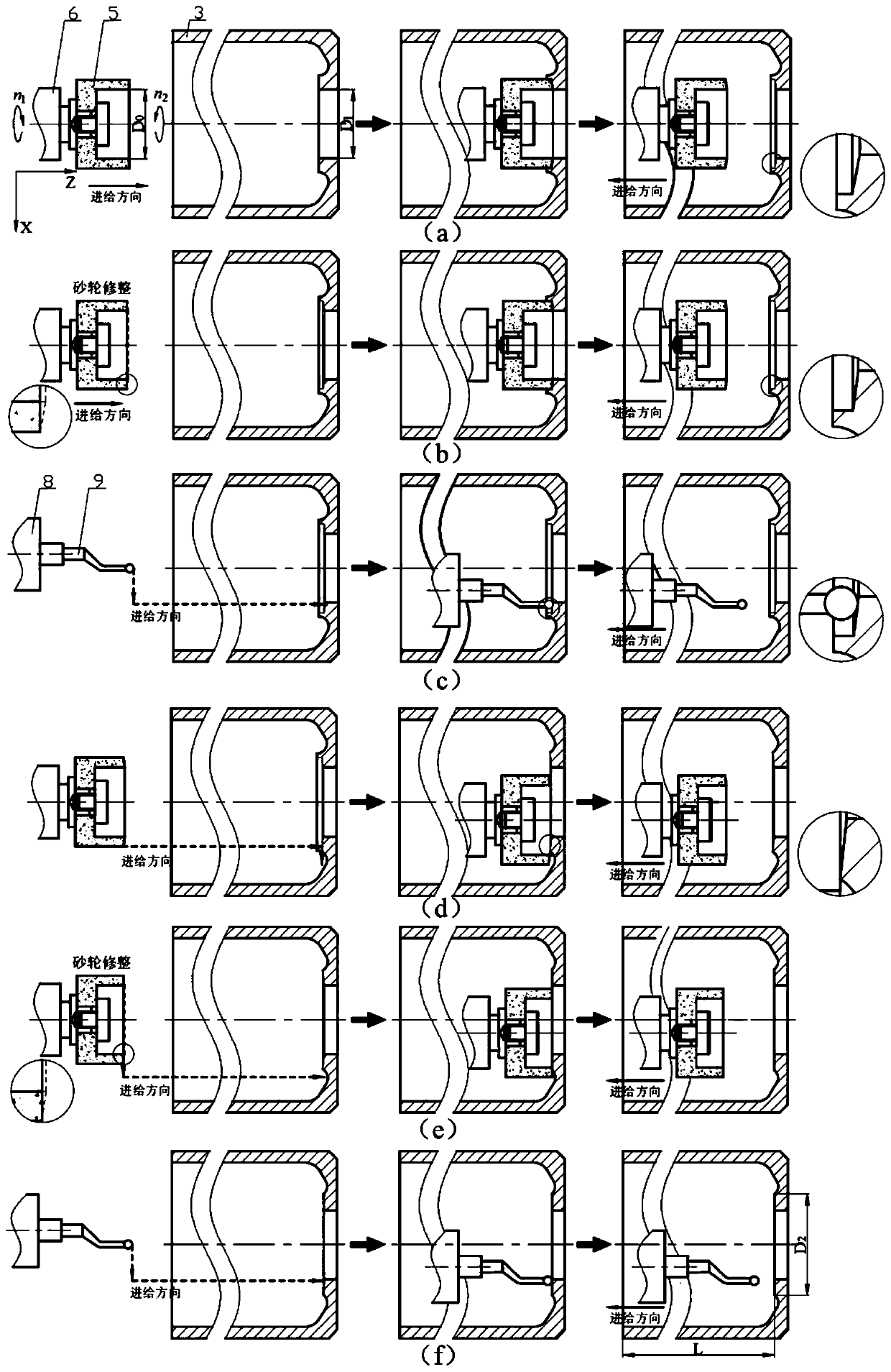
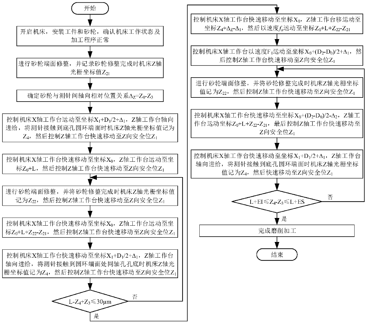
[0051] S1. Turn on the machine tool, install the workpiece 3 and the grinding wheel 5, and confirm that the working status of the machine tool and the processing program are normal.

[0052] S2. Grinding wheel dressing: control the movement of X-axis table 7 and Z-axis table 2 of the machine tool to dress the end face of the grinding wheel 5, and record the Z-axis raster coordinate value Z of the machine tool when the dressing of the grinding wheel 5 is completed 21 .

[0053] S3. Determine the axial relative positional relationship between the grinding wheel 5 and the stylus 9: control the movement of the X-axis table 7 and the Z-axis table 2 of the machine tool so that the right end surface of the grinding wheel 5 touches the left end surface of the workpiece 3, and record the Z-axis grating of the machine tool at this time Coordinate value Z 0 , and then control the X-axis table 7 and Z-axis table 2 of the machine tool to move so that the stylus 9 touches the left end surf...


PUM


Abstract

The invention discloses a processing method for grinding a circular ring end surface through a grinding rod with large slenderness ratio and weak rigidity. The processing of the circular ring end surface is divided into three steps of grinding a coaxial hole at the circular ring end surface of a bottom hole, removing the hole wall of the coaxial hole, and finish-machining the circular ring end surface of the bottom hole. In the coaxial hole processing process, the distance Z4 to Z3 between the hole bottom of the coaxial hole and the left end surface of a workpiece is measured through a probe and is differed from the nominal dimension L between the circular ring end surface of the bottom hole on a workpiece drawing and the left end surface of the workpiece; when L-Z4+Z3 is smaller than or equal to 30mum, the hole wall of the coaxial hole is removed, and finally the circular ring end surface of the bottom hole is finish-machined; and the distance between the circular ring end surface ofthe bottom hole and the left end surface of the workpiece is measured through the probe until meeting the tolerance requirement of the drawing dimension, so that grinding processing is accomplished. According to the method provided by the invention, the occurrence of the problem that according to a traditional workpiece self-rotating grinding processing method, the chattering unstability of the grinding rod caused by the functions of axial and radial grinding forces causes fast falling or local crushing of grinding wheel abrasives is avoided, the processing efficiency and the service life of agrinding wheel are improved, the rejection rate is reduced, and automation can be easily realized.

Description

technical field [0001] The invention belongs to the field of precision grinding of the end face of an inner hole circular ring, and relates to a processing method for grinding the end face of a circular ring with a large length-to-diameter ratio weak rigid grinding rod. Background technique [0002] Parts with large depth-to-diameter ratio are widely used in rocket engine cylinders, lifting equipment actuators, aircraft landing gear and other fields. The actuator is the core component of the aircraft landing gear, and its machining accuracy directly affects the performance and safety of the landing gear. The precision machining of the inner surface of the aircraft landing gear actuator includes inner holes, excessive arcs, bottom hole ring end faces, etc. , the end face of the bottom hole ring is one of the key dimensions of the actuator. It is necessary to strictly ensure the wall thickness, flatness and surface roughness of the end face of the bottom hole ring, so as to en...

Claims


Application Information

Patent Timeline
Patent Type & Authority Applications(China)
IPC IPC(8): B24B7/16B24B47/20B24B49/02B24B49/12B24B51/00B24B53/06
CPCB24B7/16B24B47/20B24B49/02B24B49/12B24B51/00B24B53/06
Inventor 朱祥龙康仁科焦振华董志刚高尚卢成
Owner DALIAN UNIV OF TECH
Learn More