Electric melting joint and interface for high-pressure pipeline system and implementation method

A technology for electrofusion joints and high-pressure pipelines, applied in the direction of pipeline connection layout, pipe/pipe joints/pipe fittings, mechanical equipment, etc., can solve problems such as erosion of fiber layer, failure, etc. to bearing capacity and the effect of

Inactive Publication Date: 2019-10-15
上海英泰塑胶股份有限公司
View PDF10 Cites 5 Cited by
  • Summary
  • Abstract
  • Description
  • Claims
  • Application Information

AI Technical Summary

Problems solved by technology

[0011] The present invention aims to solve the deficiencies in the prior art, so it proposes an electrofusion joint and interface for high-pressure pipeline systems and an implementation method to achieve high-strength connections, and at the

Method used


Image

  • Electric melting joint and interface for high-pressure pipeline system and implementation method
  • Electric melting joint and interface for high-pressure pipeline system and implementation method
  • Electric melting joint and interface for high-pressure pipeline system and implementation method

Examples


Embodiment 1

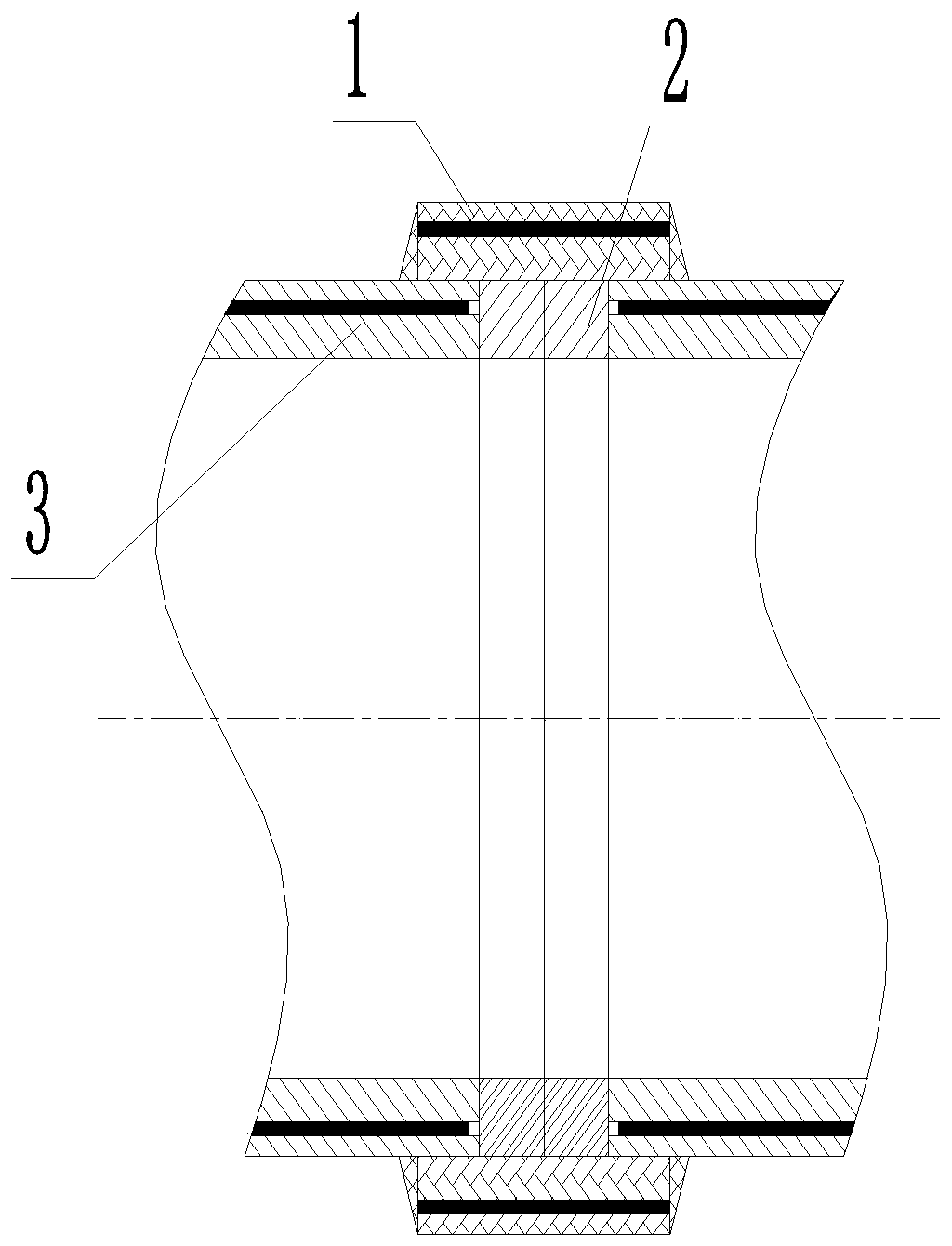
[0048] Such as figure 1 with figure 2 As shown, an electrofusion joint and interface for a high-pressure piping system. The electrofusion joint includes a thermoplastic continuous fiber core layer integrally laminated reinforced composite pipe with resistance wires laid on the inner wall. The electrofusion joint interface includes an electrofusion pipe sleeve 1 , Two short plastic pipes 2 and an external continuous fiber prepreg reinforced high-pressure composite pipe 3 connecting two short plastic pipes 2. The short plastic pipe 2 is fused with the electrofusion pipe sleeve 1 to form an anti-penetration sealing socket, and the continuous fiber is connected outside The outer wall of the prepreg reinforced high-pressure composite pipe 3 and the electric fusion pipe sleeve 1 are fused to form an anti-axial tensile and twisting socket.

[0049] Because the plastic layer of the outer tube of the external continuous fiber prepreg reinforced high-pressure composite pipe 3 is thin and t...

Embodiment 2

[0051] Such as figure 1 with image 3 As shown, the implementation method of the electrofusion joint and interface is as follows when used in the installation of new pipelines:

[0052] Step 1. Use a tapered cutter head cutter or a polishing machine to remove the fiber layer inside the outer wall of the external continuous fiber prepreg reinforced high-pressure composite pipe 3, and the removal depth is 10-30mm;

[0053] Step 1: Two plastic short tubes 2 of a certain length are fused and butt-connected with the corresponding ports of the external continuous fiber prepreg reinforced high-pressure composite tube 3 to form a butt joint;

[0054] Step 2: Use a polisher to remove the welded bumps on the inner and outer walls of the interface;

[0055] Step 3: Insert the electrofusion tube sleeve 1 from one end of the continuous fiber prepreg reinforced high-pressure composite tube 3 where the plastic short tube 2 is welded, and move the port of the electrofusion tube sleeve 1 and the plast...

Embodiment 3

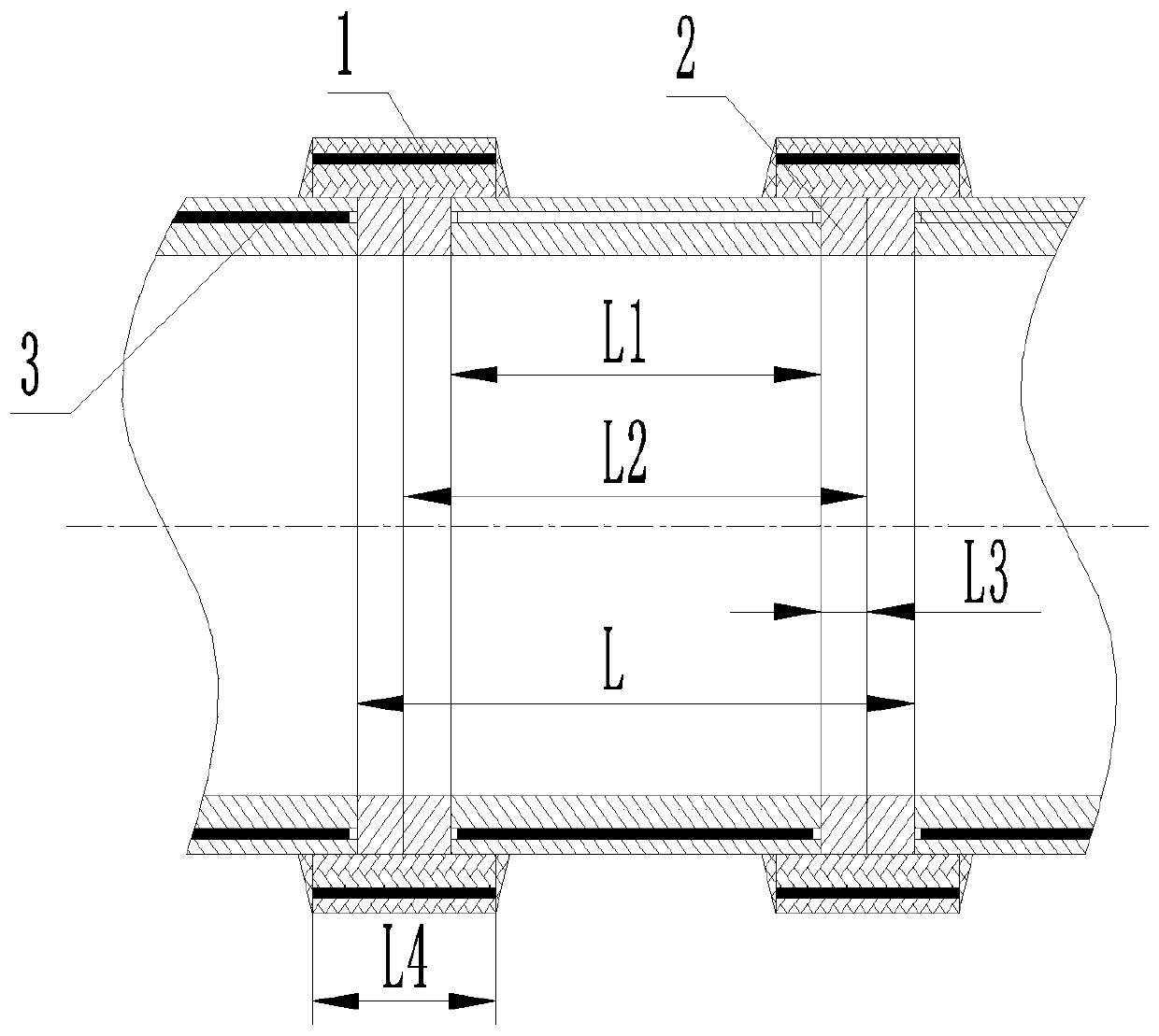
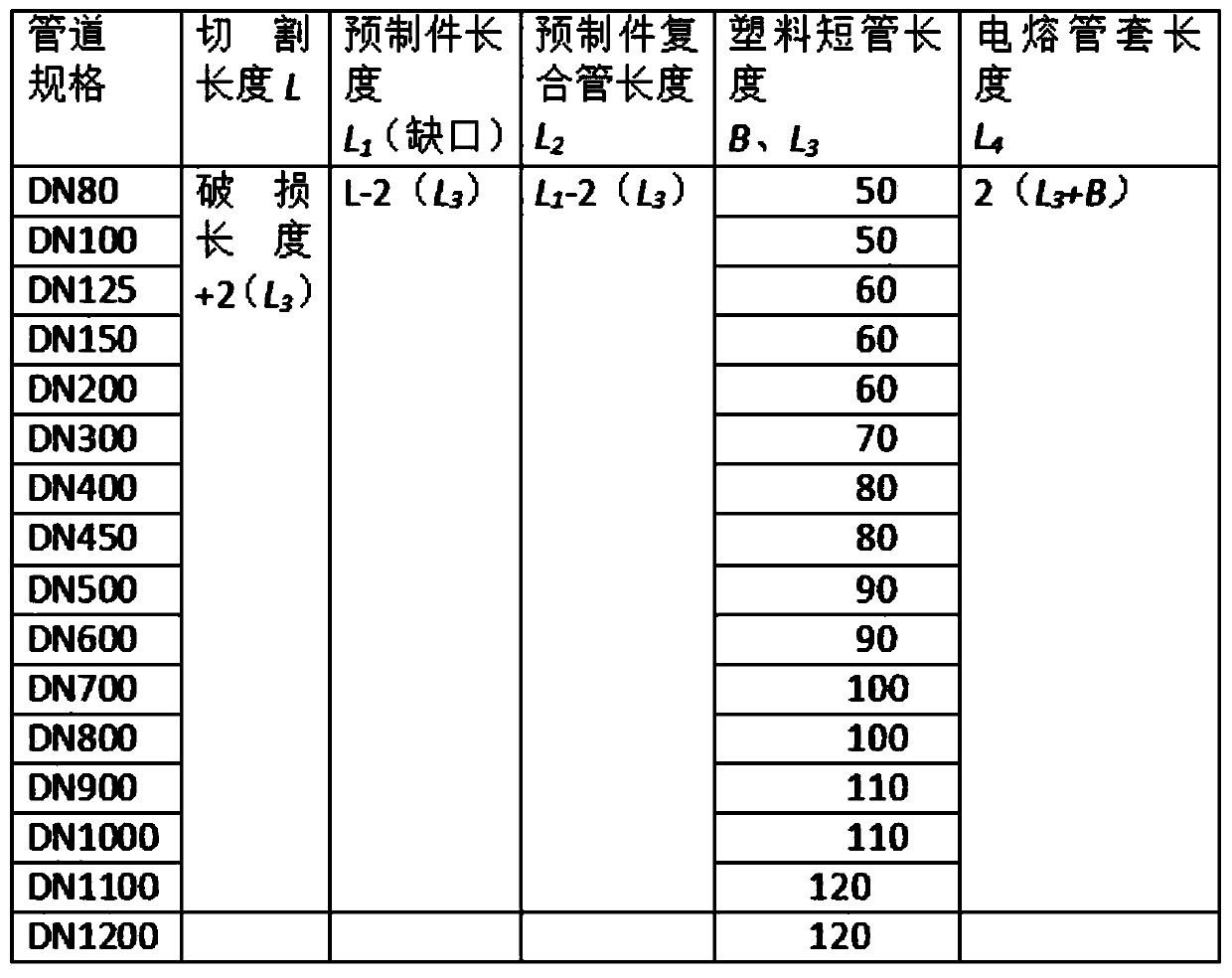
[0062] Such as figure 2 with image 3 As shown, the implementation method of the electrofusion joint and interface is used for quick repair of damaged pipelines as follows: L=damage length+2(L 3 ); L 1 =L-2(L 3 ); L 2 =L 1 -2(L 3 ); L 4 = 2(L 3 )+parameter (B); L: total length of pipe cutting; L 1 : Length of preform (notch); L 2 :Length of prefabricated composite pipe; L 3 :The length of short plastic pipe (tensile and shear length); L 4 : Length of electrofusion joint; B: Length of tensile and shear.

[0063] A1. According to the situation of the damaged pipe, close the nearby gate valve and drain the medium in the pipe in time;

[0064] A2, use a tape measure to measure the length of the damaged pipe + 2L 3 As cutting pipe length L, L 3 Is a short plastic tube 2;

[0065] A3. After using a tape measure circle as a support and marking the line with a marker pen, use a portable cutter to neatly cut along the marker line to form two pipe ports with a distance of L 2 ;

[0066] A4. Us...


PUM


Abstract

The invention discloses an electric melting joint and an interface for a high-pressure pipeline system and an implementation method, and belongs to the technical field of electric melting tube sleeves. The electric melting joint comprises a thermoplastic continuous fiber tape core layer integral layered reinforced composite tube laid with a resistance wire on the inner wall, the electric melting joint and the interface comprises an electric melting pipe sleeve, two plastic short pipes and an external continuous fiber prepreg tape reinforced high-pressure composite pipe which is connected withthe two plastic short pipes, and the plastic short pipes and the electric melting pipe sleeve are fused to form an anti-permeation sealing socket, and the outer wall of the external continuous fiber prepreg tape reinforced high-pressure composite pipe and the electric melting pipe sleeve are fused to form an anti-axial anti-tensile twisting socket. The fiber prepreg tape reinforced high-pressure composite pipe is used for sealing a fiber layer by utilizing the plastic short pipes, the compression resistance and tensile resistance at the joint are enhanced, the construction amount is greatly reduced in the implementation process, so that an electric smelting pipe fitting can quickly weld a newly-built pipeline or a damaged pipeline for connection or repair.

Description

Technical field [0001] The invention belongs to the technical field of electric fusion pipe sleeves, and particularly relates to an electric fusion joint and interface used in a high-pressure pipeline system and an implementation method. Background technique [0002] In the process of thermoplastic pipe connection, the connection between the pipes or the connection between the pipe and the elbow or the tee can be used to heat the hot melt extrusion connection of the mold and the resistance electric fusion sleeve to the molten pool to melt the pressure connection pipe interface. Compared with the mold hot melt method, the electrofusion connection has the advantages of single process, lighter equipment, and high power of interface fusion, especially in small spaces. The advantages are more obvious. [0003] Thermoplastic continuous fiber reinforced composite piping system, in a large number of applications, from the installation process, the weld joint is often not strong enough and ...

Claims


Application Information

Patent Timeline
IPC IPC(8): F16L47/03
CPCF16L47/03
Inventor 林世平
Owner 上海英泰塑胶股份有限公司
Why Eureka
Try Eureka