Impedance matching high-gain lens antenna and design method thereof

An impedance matching, lens antenna technology, applied in the direction of antenna, radiating element structure, electrical components, etc., can solve problems such as poor directivity, and achieve the effect of small size, wide working bandwidth, and reduced side lobe level.

Active Publication Date: 2019-10-15
SOUTHEAST UNIV
View PDF5 Cites 6 Cited by
  • Summary
  • Abstract
  • Description
  • Claims
  • Application Information

AI Technical Summary

Problems solved by technology

The radiation wave of the traditional H-plane fan-shaped horn antenna is in the form of a cylindrical surface wave, a

Method used


Image

  • Impedance matching high-gain lens antenna and design method thereof
  • Impedance matching high-gain lens antenna and design method thereof
  • Impedance matching high-gain lens antenna and design method thereof

Examples


Embodiment Construction

[0055] The present invention will be further described below in combination with specific embodiments and accompanying drawings.

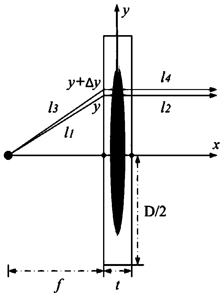
[0056] An impedance-matched high-gain lens antenna, comprising an impedance-matching lens and an H-plane fan-shaped horn antenna loaded with a waveguide extension, the aperture of the H-plane fan-shaped horn antenna is connected to a waveguide extension of the same caliber to fix the impedance-matching lens; The length of the waveguide extension section is equal to the thickness of the impedance matching lens, and is used to fix the impedance matching lens and completely cover its sides. The electromagnetic wave signal excited from the signal source passes through the H-shaped fan-shaped horn antenna, radiating cylindrical waves, and the cylindrical waves pass through the impedance matching lens, the phase is corrected, and transformed into a two-dimensional plane wave whose equiphase plane is perpendicular to the propagation direction, and finally ...


PUM


Abstract

The invention discloses an impedance matching high-gain lens antenna and a design method thereof. The impedance matching high-gain lens antenna comprises an impedance matching lens and an H-plane fanhorn antenna for loading a waveguide extension, wherein the aperture of the H-plane extension horn antenna is connected with the waveguide extension having the same aperture diameter for fixing the impedance matching lens; and the waveguide extension has a length equal to the width of the impedance matching lens for fixing the impedance matching lens and completely covering the side of the impedance matching lens. An electromagnetic wave signal excited from a signal source radiates a cylindrical wave through the H-plane fan horn antenna. The phase of the cylindrical wave is corrected by the impedance matching lens so that the cylindrical wave is converted into a two-dimensional plane wave having an equiphase surface perpendicular to the propagation direction and finally radiating to the free space. The lens antenna has a working frequency bandwidth, low loss, high gain, good far-field directionality, low sidelobe level, a small size and the like, can work normally in the X-band, and has high practicality in electromagnetic imaging and communication fields.

Description

technical field [0001] The invention relates to an impedance-matched high-gain lens antenna, which belongs to the field of novel artificial electromagnetic devices and a design method thereof. Background technique [0002] As a device that effectively receives and radiates electromagnetic waves, the antenna's directivity is an important indicator to measure its performance. The radiation wave of the traditional H-plane fan-shaped horn antenna is in the form of a cylindrical surface wave, and there is a large phase deviation between the central radiation area and the edge area, and the directivity is poor. The function of the lens is to correct the phase wavefront from the radiation source, reduce the phase deviation between the center and the edge of the wavefront, and improve the directivity. Compared with the traditional antenna, the lens antenna has more controllable parameters, the medium, shape and focal diameter ratio of the lens can be adjusted, the design is flexibl...

Claims


Application Information

Patent Timeline
IPC IPC(8): H01Q19/08H01Q19/06H01Q15/08H01Q13/02H01Q1/36
CPCH01Q1/36H01Q13/02H01Q13/0283H01Q15/08H01Q19/062H01Q19/08
Inventor 蒋卫祥张娜田翰闱崔铁军
Owner SOUTHEAST UNIV
Why Eureka
Try Eureka