Manufacturing process of optical fiber preform

An optical fiber preform and manufacturing process technology, which is applied to manufacturing tools, glass manufacturing equipment, glass deposition furnaces, etc., can solve the problems of internal airflow disturbance, large size of the torch, affecting the deposition quality of silica particles, etc., and achieve spatial disturbance. The effect of reducing, good deposition quality and ensuring deposition efficiency

Active Publication Date: 2021-09-21
FUTONG GRP JIASHAN COMM TECH CO LTD +1
View PDF6 Cites 0 Cited by
  • Summary
  • Abstract
  • Description
  • Claims
  • Application Information

AI Technical Summary

Problems solved by technology

[0003] When the existing OVD method is used to manufacture the outer cladding (loose body) of the optical fiber preform, the blowtorch moves back and forth along the length direction of the mandrel. The blowtorch is relatively large in size and has a certain disturbing effect on the internal airflow when it moves, which will affect the deposition of silica particles. quality

Method used


Image

  • Manufacturing process of optical fiber preform
  • Manufacturing process of optical fiber preform
  • Manufacturing process of optical fiber preform

Examples


Embodiment Construction

[0045] Below in conjunction with each accompanying drawing, the present invention is described in detail.

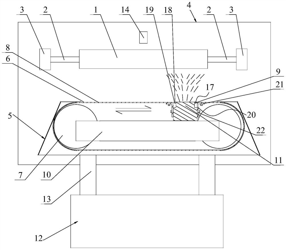
[0046] A manufacturing process for an optical fiber preform, comprising the following steps:

[0047] 1) An auxiliary rod is welded at both ends of the mandrel, and the two auxiliary rods are respectively clamped on two chucks, and the chuck drives the auxiliary rod and the mandrel to rotate;

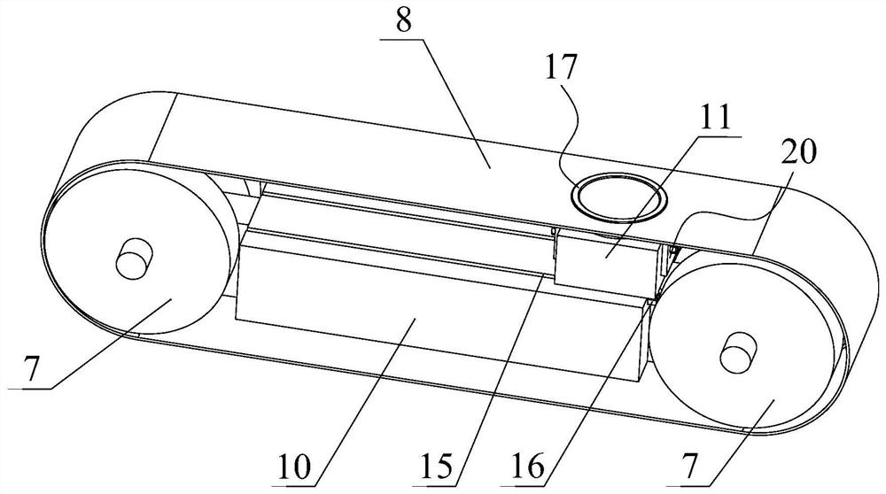
[0048] 2) Set the conveyor belt under the mandrel, the conveyor belt is provided with a through hole, set the blowtorch inside the conveyor belt and connect with the conveyor belt, and the nozzle of the blowtorch is located inside the through hole or flush with the upper surface of the conveyor belt through the through hole, and the conveyor belt reciprocates The movement drives the blowtorch to reciprocate along the length direction of the mandrel, and the blowtorch makes the outer surface of the mandrel precipitate loose particles;

[0049] 3) Measure the outer diameter of the ...


PUM


Abstract

The application discloses a manufacturing process of an optical fiber preform, which includes the following steps: 1) welding an auxiliary rod at both ends of the core rod, respectively clamping the two auxiliary rods on two chucks, and the chuck drives Auxiliary rod and mandrel rotation; 2) conveyer belt is set under the mandrel, and conveyer belt is provided with through hole, blowtorch is arranged on conveyer belt inner side and is connected with conveyer belt, and the nozzle of blowtorch is positioned at through hole inner side or passes through through hole and conveyer belt The upper surface is flush, and the reciprocating movement of the conveyor belt drives the blowtorch to reciprocate along the length direction of the mandrel, and the blowtorch makes the outer surface of the mandrel precipitate loose particles. The nozzle of the blowtorch of this application is located inside the through hole or passes through the hole and is flush with the upper surface of the conveyor belt. The driving belt drives the blowtorch to move. Compared with the existing structure, the disturbance of the space caused by the reciprocating movement of the blowtorch is greatly reduced. Silica The deposition quality of the particles is better.

Description

technical field [0001] The invention relates to the field of optical fiber preformed rods, in particular to a manufacturing process of optical fiber preformed rods. Background technique [0002] In the OVD method, the blowtorch mixes silicon tetrachloride or octamethylcyclotetrasiloxane vaporized gas with oxygen, and sprays it together with hydrogen (or methane) and oxygen flames to the rotating target rod. Under the action of heat energy, the raw materials A hydrolysis reaction occurs to generate silica, and the dust particles produced by the pyrolysis of silica particles are adsorbed layer by layer on the rotating target rod passing through the flame to form a porous preform embryo body (also called loose body), and the resulting porous preform The rod body is passed through a desiccant (for example, chlorine gas) at a temperature ranging from 1100°C to 1550°C to remove impurities such as hydroxyl groups, sintered into a glass preform, and then drawn into an optical fiber....

Claims


Application Information

Patent Timeline
Patent Type & Authority Patents(China)
IPC IPC(8): C03B37/014
CPCC03B37/0142C03B37/014C03B2207/66Y02P40/57
Inventor 杨军勇朱晓波董瑞洪徐旻凯
Owner FUTONG GRP JIASHAN COMM TECH CO LTD
Why Eureka
Try Eureka