Hydraulic impactor

A technology of hydraulic impactor and piston, which is applied to the driving device for drilling in the borehole, earthwork drilling and production, drilling equipment, etc., and can solve the problem of complex structure of hydraulic impactor, poor practicability of high-energy impactor, and multiple control and switching channels and other problems, to achieve the effect of improving the drilling footage speed, single impact energy and impact frequency, and good work reliability

Pending Publication Date: 2019-10-18
JILIN UNIV
View PDF2 Cites 4 Cited by
  • Summary
  • Abstract
  • Description
  • Claims
  • Application Information

AI Technical Summary

Problems solved by technology

At present, this technology mainly enters the Chinese market in the form of technical services, but this kind of hydraulic impactor has a complex structure, many control and switching channels, and has high requirements for the driving flushing fluid. It needs to be equipped with solid control equipment to purify the flushing fluid, and the cost of use is high.
The stroke differential high-energy hydraulic down-the-hole hammer disclosed in the prior art (see CN201410756548 for details) and the high-energy impactor described in the valve-type high-energy hydraulic down-the-hole hammer (see CN201420513172 for details) have complex structures and many control and switching channels , the output piston rod is slender, and the structure is difficult to meet the requirements of large impact energy, and the practicability as a high-energy impactor is relatively poor

Method used


Image

  • Hydraulic impactor
  • Hydraulic impactor
  • Hydraulic impactor

Examples


Embodiment Construction

[0027] In order to illustrate the present invention more clearly, the present invention will be further described below in conjunction with preferred embodiments and accompanying drawings. It should be understood by those skilled in the art. The content specifically described below is illustrative rather than restrictive, and should not limit the protection scope of the present invention. "First", "second", and "third" used in the present invention do not indicate any order, quantity or importance, but are only used to distinguish different components.

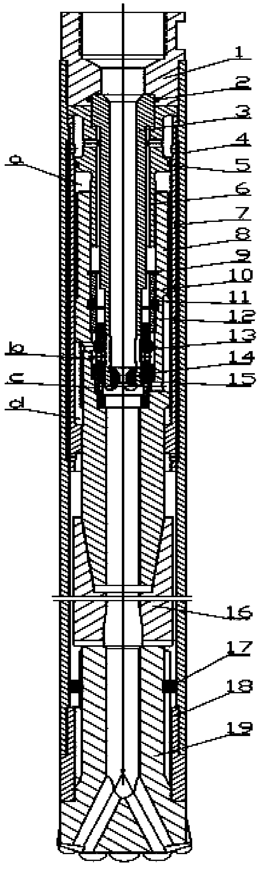
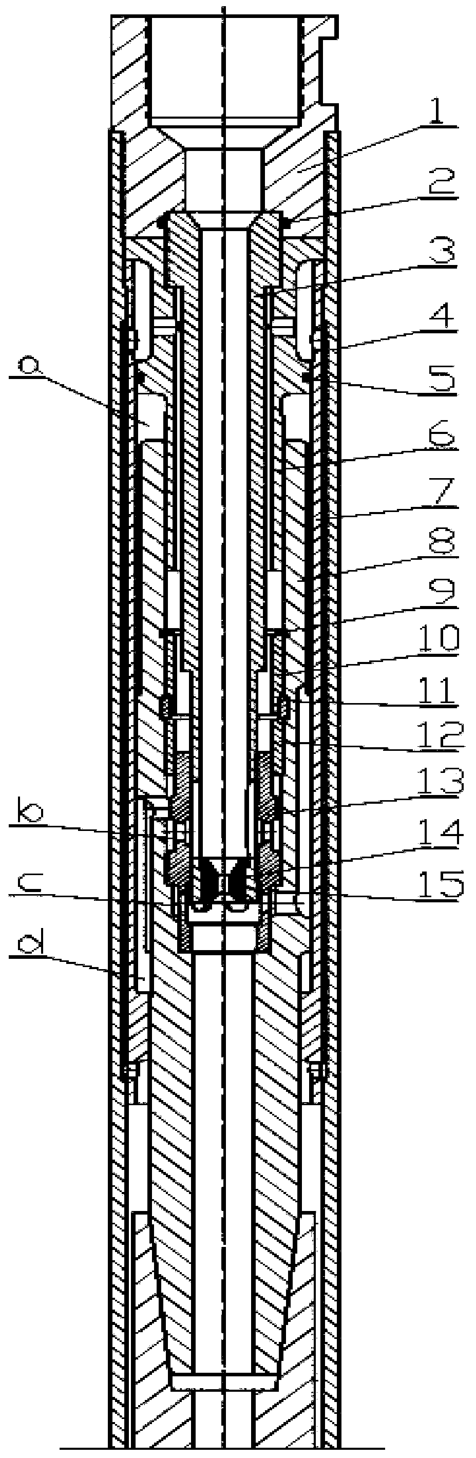
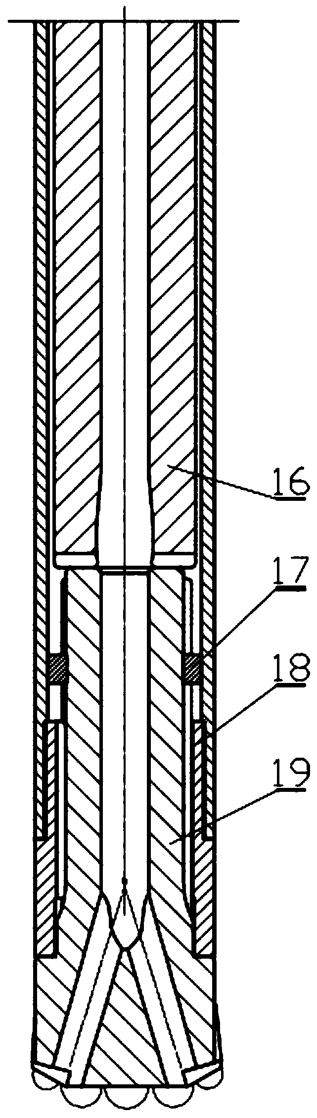
[0028] Such as figure 1 , figure 2 , image 3 , Figure 6 , Figure 7 and Figure 8As shown, a hydraulic impactor includes an upper joint 1, a distribution core tube 3, an outer tube 4, a distribution seat 6, a cylinder liner 7, a piston 8, a retaining ring 9, a retaining sleeve 10, a first semicircle clamp 11, a limiter Bit sleeve 12, control valve 13, plug 14, impact hammer 16, second semicircle clamp 17, spline slee...


PUM


Abstract

The invention discloses a hydraulic impactor, and belongs to the field of hole bottom power machines. The hydraulic impactor is driven by a pressure rinsing liquid medium to work and comprises an upper joint, a flow distribution core tube, an outer tube, a flow distribution seat, a cylinder sleeve, a piston, a jump ring, a retaining sleeve, a first semi-circular clamp, a limit sleeve, a control valve, a plug, a punch hammer, a second semi-circular clamp, a spline sleeve and a drill bit. The impactor is simple in structure, small in volume loss and pressure loss and high in energy utilization rate, has the wide-spectrum working characteristics, can meet large ballistic work output requirements on the structure, can implement impact rotation drilling with rotation as main under the working condition with small flow, can implement impact rotation drilling with impacting as main under the working condition with large flow, improves the drilling footage speed in a multiplied manner, helps to reduce the construction cost of the fields of petroleum and water well drilling, mine and geological prospecting and the like, and particularly helps to accelerate the development and utilization ofnew energy dry hot rock.

Description

technical field [0001] The invention relates to a drilling / hole drilling tool for drilling rocks, which belongs to the field of hole bottom power machines, and can be applied to geological exploration, hydrology and water well drilling, oil drilling, geothermal wells and other rock and soil drilling, especially can be applied to deep dry Rapid drilling in hot rock. Background technique [0002] At present, in geological exploration, hydrology and water well drilling, oil drilling and geothermal well drilling, etc., in various drillings such as rapid drilling of deep dry hot rocks, hydraulic impactors can be used to realize hydraulic impact rotary drilling. , can increase the footage speed of drilling into hard rock, and is an effective drilling method to solve the problem of drilling into hard rock. However, this kind of hydraulic impact rotary drilling is mainly rotary drilling, supplemented by impact. For example, diamond rope coring impact rotary drilling is based on dia...

Claims


Application Information

Patent Timeline
Patent Type & Authority Applications(China)
IPC IPC(8): E21B4/16E21B4/00
CPCE21B4/003E21B4/16
Inventor 杨红东王茂森高科郑治川计胜利彭枧明博坤
Owner JILIN UNIV
Why Eureka
Try Eureka