
Preheating ignition method and device for electric melting furnace

A technology of electric melting and charge, which is applied in the field of preheating ignition method and device of electric melting furnace, can solve problems such as unstable arc combustion, large amount of smoke generated, unbalanced three-phase current, etc., and achieves outstanding substantive features, The effect of fast arc speed and three-phase current balance

Active Publication Date: 2019-10-22
北京金亚润环保科技有限公司
View PDF9 Cites 2 Cited by
  • Summary
  • Abstract
  • Description
  • Claims
  • Application Information

AI Technical Summary

Problems solved by technology

The first kind of fuel combustion melting furnace is divided into surface combustion melting furnace, cyclone melting furnace, etc., its disadvantage is that it produces a large amount of smoke and the tail gas treatment is complicated
The second type of electric melting furnace is divided into resistance furnace, electric arc furnace, plasma furnace, etc. The disadvantages are large power consumption and high maintenance costs.
[0004] However, there are the following problems in the arcing and ignition method of the electric melting furnace at the beginning of operation: first, the three-phase electrodes are inconsistent in arcing inside the electric melting furnace, resulting in an unbalanced three-phase current, and it is an instantaneous irregular three-phase current imbalance , which will cause malfunction of electrical equipment; second, the three-phase electrodes have intermittent arcing inside the electric melting furnace, sometimes short-circuited, sometimes arc-broken, the arc combustion is unstable, and the voltage and current fluctuate greatly, which requires repeated points The arc will cause a great impact on the power grid, and may generate high-order harmonics that will pollute the power grid and affect the safe operation of the power grid

Method used


Image

  • Preheating ignition method and device for electric melting furnace
  • Preheating ignition method and device for electric melting furnace

Examples


Embodiment Construction

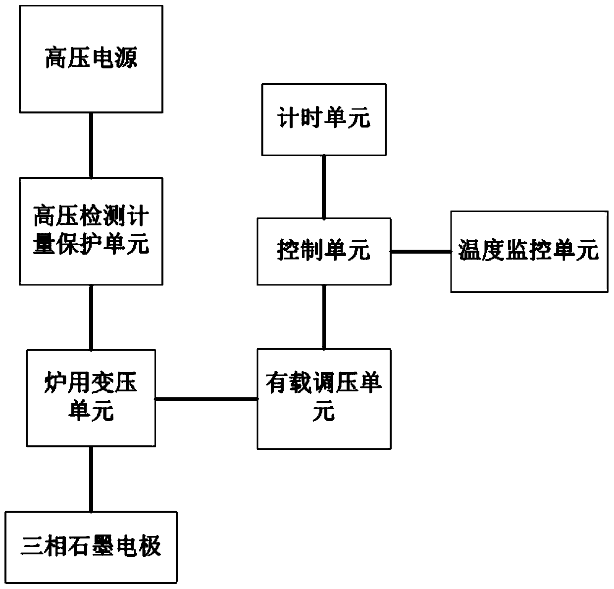
[0036] Specific embodiments of the present invention will be described below in conjunction with the accompanying drawings.

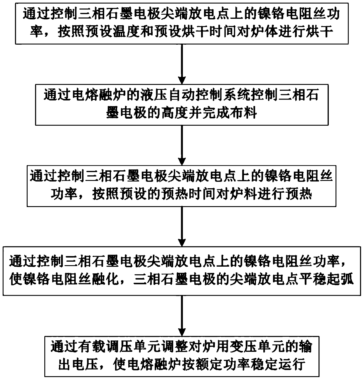
[0037] Such as figure 1 Shown a kind of preheating ignition method that is used for electric fusion furnace, comprises the steps:

[0038] Step 1: By controlling the heating power of the nickel-chromium resistance wire at the tip discharge point of the three-phase graphite electrode, the furnace body is dried according to the preset temperature and preset drying time.

[0039] This step realizes the drying of the furnace body before the operation of the electric melting furnace. At the discharge point at the tip of the three-phase graphite electrode, the three phases are respectively connected (the three-phase graphite electrode head can be drilled with a thread, and the resistance wire joint can be crimped with a screw and a flat pad) 30kW nickel-chromium resistance wire, through the on-load voltage regulation The unit adjusts the low-end voltage to ...


PUM


Abstract

The invention provides a preheating ignition method and device for an electric melting furnace. The preheating ignition method and device are used for producing rock wool by using red mud. A large-power nickel-chromium resistance wire is additionally introduced to a point discharge point of a three-phase graphite electrode for preheating and serving as an ignition device to dry the interior of a novel electric melting furnace, preheat furnace materials and realize stable transition after electric arc ignition through the three-phase electrode. The electric melting furnace is high in electric arc ignition speed, steady one-time arc ignition can be achieved, the three-phase current is balanced, and automatic or manual control can be realized. The voltage and the current do not fluctuate severely. Unstable electric arc burning does not exist. Short circuit and arc breaking are avoided. The preheating ignition method and device have no impact on a power grid and are free of harmonic pollution in the implementation process.

Description

technical field [0001] The invention relates to the technical field of electric melting furnace ignition, and more specifically relates to a preheating ignition method and device for an electric melting furnace. Background technique [0002] At present, there are two types of representative melting furnaces on the market: the first type is a fuel-burning melting furnace, and the second type is an electric melting furnace. The first kind of fuel combustion melting furnace is divided into surface combustion melting furnace, cyclone melting furnace, etc., and its disadvantage is that it produces a large amount of smoke and the tail gas treatment is complicated. The second type of electric melting furnace is divided into resistance furnace, electric arc furnace, plasma furnace, etc. The disadvantages are large power consumption and high maintenance costs. The electric melting furnace is widely used because of its advantages of less pollution and high degree of automation. [0...

Claims


Application Information

Patent Timeline
Patent Type & Authority Applications(China)
IPC IPC(8): F23Q3/00F27B14/14
CPCF23Q3/002F27B14/14
Inventor 张勇张银国王靖然史鑫张欣张晓义俞青平
Owner 北京金亚润环保科技有限公司
Learn More