
Variable-reluctance zero-offset setting method for alternating-current permanent magnet motor

A permanent magnet motor and permanent magnet synchronous motor technology, which is applied in the control of generators, motor generator control, electronic commutation motor control, etc., can solve the problems of motor torque loss, excessive, and many additional conditions, etc. The influence of resistance torque and friction force, simple operation method, and the effect of saving manpower and material resources

Inactive Publication Date: 2019-10-22
格至控智能动力科技(上海)有限公司
View PDF4 Cites 2 Cited by
  • Summary
  • Abstract
  • Description
  • Claims
  • Application Information

AI Technical Summary

Problems solved by technology

[0005] Method 1 defect: There are too many additional conditions in the implementation, and additional equipment such as another steady-speed motor, pair-towing platform, and two power supply cabinets need to be added
[0007] The defect of method 2: Since the reluctance torque and friction force of each permanent magnet motor are different, the required current is different, so the use of DC current gun has the problem of weak adaptability, and the difference in hardware also causes the There will be a deviation in the zero position, which will lead to poor motor control accuracy or cause the torque of the motor to be missing or too large.

Method used


Image

  • Variable-reluctance zero-offset setting method for alternating-current permanent magnet motor
  • Variable-reluctance zero-offset setting method for alternating-current permanent magnet motor
  • Variable-reluctance zero-offset setting method for alternating-current permanent magnet motor

Examples


Embodiment 1

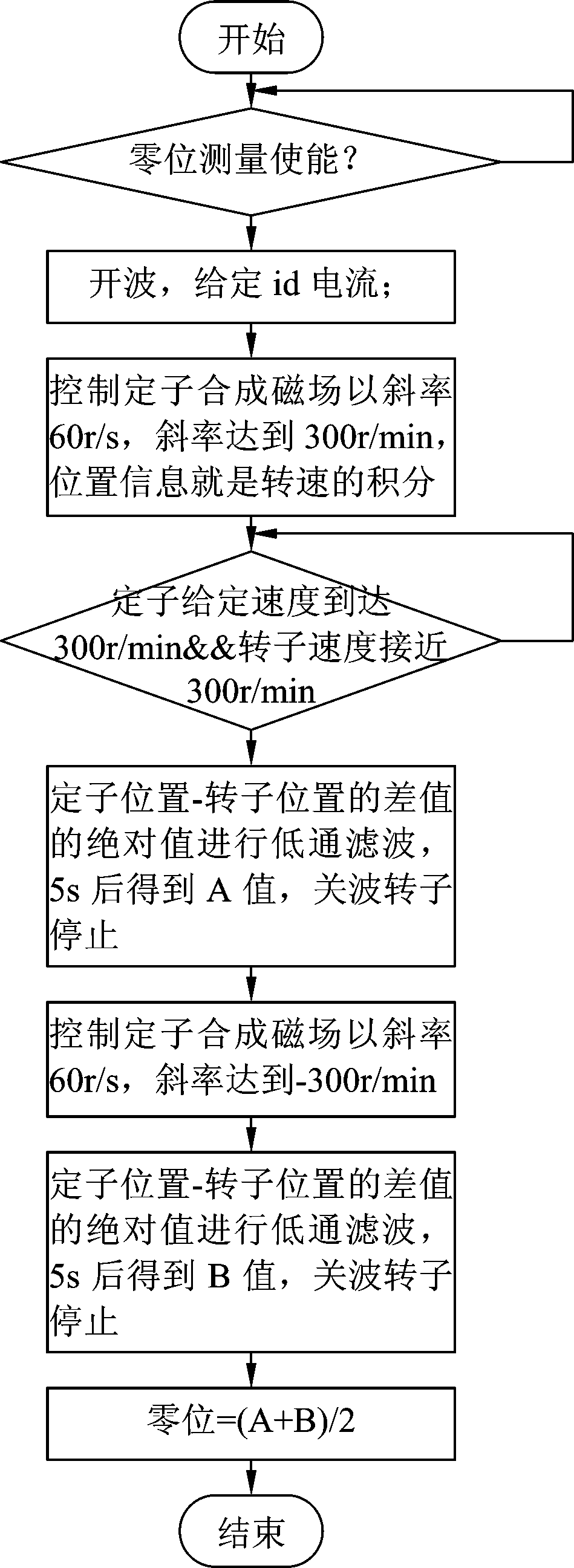
[0033] A resolver zero bias setting method for AC permanent magnet motors, such as figure 1 Shown: Follow the steps below to implement in sequence:

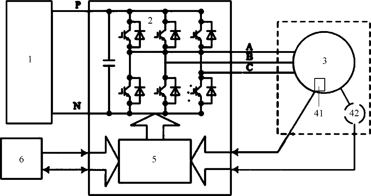
[0034] ① Connect the motor: normally connect the motor, electric control low-voltage and high-voltage wiring harness, that is, figure 2 As shown: the high-voltage direct current output by the high-voltage direct current power supply 1 is converted into three-phase alternating current by the inverter 2, and the phase A, phase B and phase C of the three-phase alternating current are respectively connected to the phase A terminal, the phase B terminal and the phase B terminal of the permanent magnet synchronous motor 3 C phase terminal, permanent magnet synchronous motor 3 is provided with temperature sensor 41 and resolver 42, temperature sensor 41 and position sensor 42 are all connected motor controller 5 by signal line, motor controller 5 obtains by temperature sensor 41 and position sensor 42 The temperature information and p...


PUM


Abstract

The invention relates to the field of motor testing, in particular to a variable-reluctance zero-offset setting method for an alternating-current permanent magnet motor, and relates to a variable-reluctance zero-offset setting method for an alternating-current permanent magnet motor. The method comprises the following steps of: (1) connection of a motor; (2) communication; (3) enabling; (4) zero measuring; and (5), calibration. The variable-reluctance zero-offset setting method is simple in device, convenient to test and accurate in result.

Description

technical field [0001] The invention relates to the field of motor testing, in particular to a method for setting the zero bias of a resolver for an AC permanent magnet motor. Background technique [0002] At present, for AC permanent magnet motors, especially permanent magnet drive motors used in new energy vehicles, in terms of motor control, an important indicator is the smooth and fast response of the motor torque. In motor control, the smooth and fast response of the motor torque is directly related to the current. In the implementation process of the existing control method, the position signal of the motor is a very important control variable, which has a great influence on the quality and precision of the control. At present, the position sensor is used on the motor to measure the real-time position of the motor and apply it to the control. For the permanent magnet synchronous motor, the initial position of the motor, that is, the zero position, is a very important ...

Claims


Application Information

Patent Timeline
Patent Type & Authority Applications(China)
IPC IPC(8): H02P21/14
CPCH02P21/14
Inventor 杨佳亮
Owner 格至控智能动力科技(上海)有限公司
Learn More