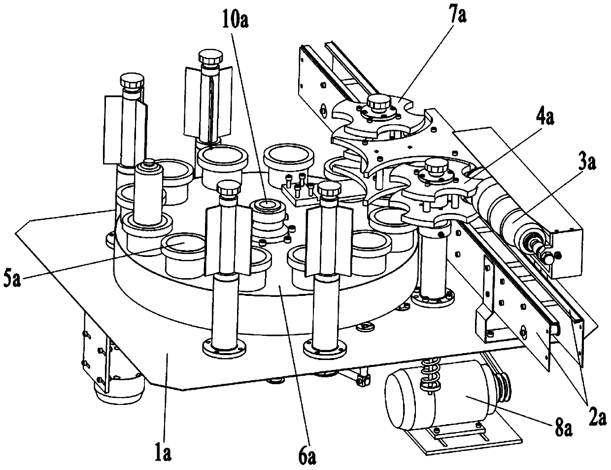
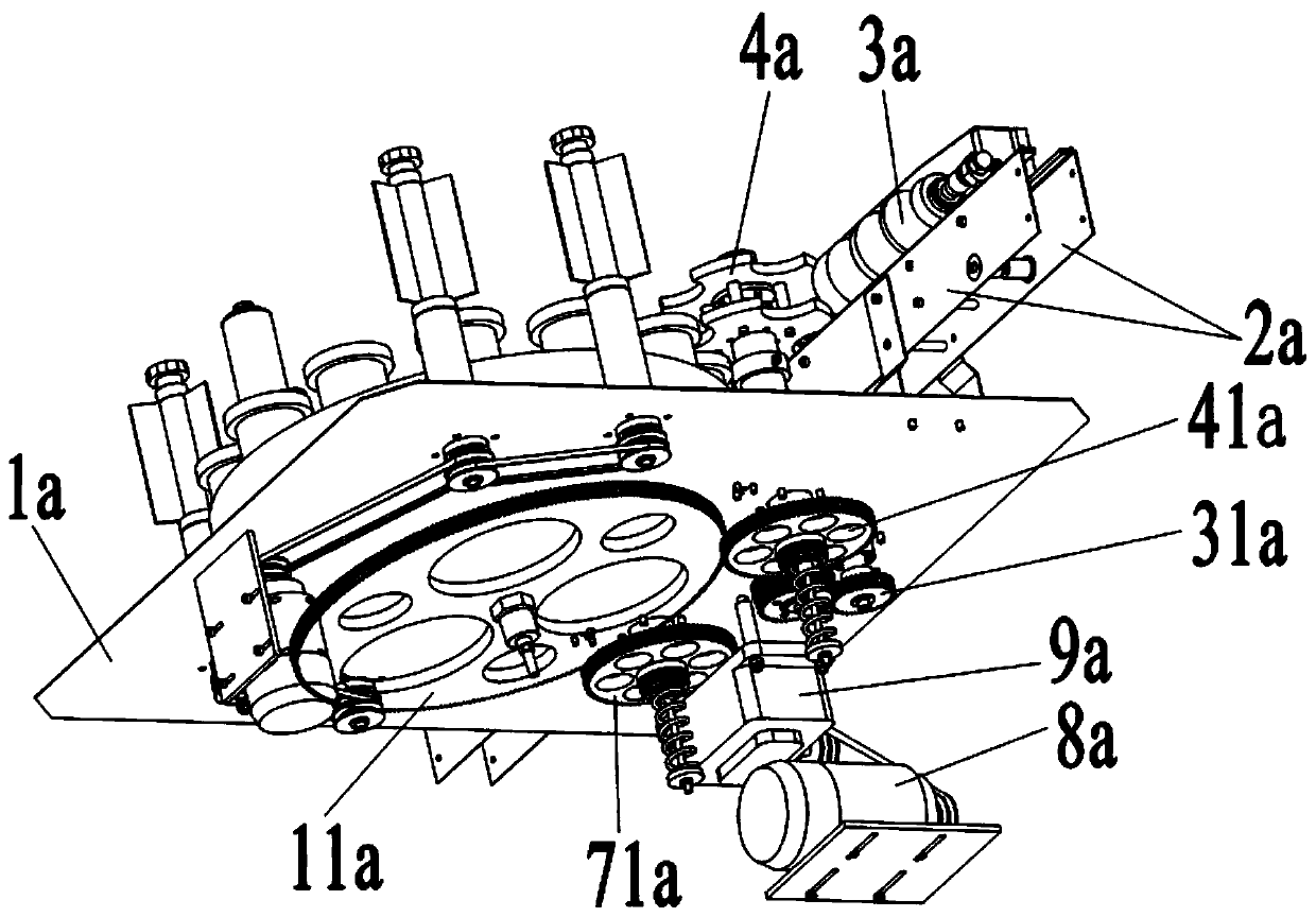
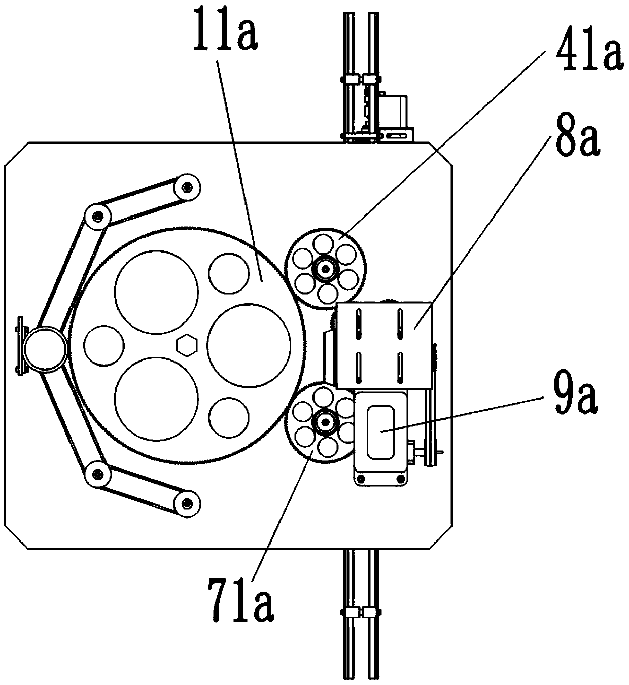
Conveying mechanism and inner wall cleaning mechanism and outer wall cleaning mechanism and reagent bottle cleaning machine

A transmission mechanism and inner wall cleaning technology, applied in the inner wall cleaning mechanism, outer wall cleaning mechanism and reagent bottle cleaning machine, transmission mechanism field, can solve the problems of manual intervention, high labor intensity, long working cycle, etc., to ensure a sterile environment , reliable action and high cleaning efficiency

Inactive Publication Date: 2019-10-25
广州纳航渔业服务有限公司
View PDF5 Cites 15 Cited by
  • Summary
  • Abstract
  • Description
  • Claims
  • Application Information

AI Technical Summary

Problems solved by technology

[0004] At present, the cleaning of reagent bottles before sterilization is done manually or by a single simple automatic cleaning station.
This cleaning method not only has high labor intensity and long working cycle, but also requires a lot of manual intervention in the operation process, which can easily cause drug residues inside the reagent bottle and cause secondary pollution to the reagent bottle.

Method used


Image

  • Conveying mechanism and inner wall cleaning mechanism and outer wall cleaning mechanism and reagent bottle cleaning machine
  • Conveying mechanism and inner wall cleaning mechanism and outer wall cleaning mechanism and reagent bottle cleaning machine
  • Conveying mechanism and inner wall cleaning mechanism and outer wall cleaning mechanism and reagent bottle cleaning machine

Examples


Embodiment Construction

[0028] Exemplary embodiments of the present disclosure will be described in more detail below with reference to the accompanying drawings, these embodiments are for a more thorough understanding of the present invention and can fully convey the scope of the present disclosure to those skilled in the art. While the drawings show exemplary embodiments of the present disclosure, it is to be understood that the invention is not to be limited to the embodiments set forth herein.

[0029] In describing the present invention, it should be understood that the terms "longitudinal", "transverse", "upper", "lower", "front", "rear", "left", "right", "vertical", The orientations or positional relationships indicated by "horizontal", "top", "bottom", "inner", "outer", etc. are based on the orientations or positional relationships shown in the drawings, and are only for the convenience of describing the present invention, rather than indicating or It should not be construed as limiting the i...


PUM


Abstract

The invention provides a conveying mechanism, an inner wall cleaning mechanism, an outer wall cleaning mechanism and a reagent bottle cleaning machine. The reagent bottle cleaning machine comprises asupport A which is of a frame structure, wherein bottom access doors B are arranged at the four sides of the bottom of the support A; middle access doors C are arranged at the four sides of the middleof the support A; transparent inspection windows D are arranged at the four sides of the top of the support A; and a transverse beam plate E is arranged on the upper surface of the support A. The reagent bottle cleaning machine also comprises the conveying mechanism a, the inner wall cleaning mechanism b, and the outer wall cleaning mechanism c. The conveying mechanism a, the inner wall cleaningmechanism b, and the outer wall cleaning mechanism c are used in cooperation with each other. The reagent bottle cleaning machine can complete various work tasks such as conveying, inner wall cleaning, outer wall cleaning and unloading of reagent bottles, is reliable in action and has high cleaning efficiency. When the reagent bottle cleaning machine works, an ultraviolet lamp works to sterilize and disinfect the reagent bottles, so that sterile environments are ensured. At the same time, a cleaning liquid recovery mechanism is used for collecting cleaning liquid after the reagent bottles arecleaned.

Description

technical field [0001] The invention relates to the field of biotechnology or pharmaceutical machinery technology, in particular to a transmission mechanism, an inner wall cleaning mechanism, an outer wall cleaning mechanism and a reagent bottle cleaning machine. Background technique [0002] Reagent bottles are an indispensable container carrier in the pharmaceutical industry. They are widely used and are divided into wide-mouth, narrow-mouth, ground-mouth and non-ground-mouth types. Wide-mouth bottles are used to hold solid reagents, and narrow-mouth bottles are used to hold liquids. Reagents; brown bottles are used for reagents protected from light, and ground stopper bottles can prevent reagents from absorbing moisture and changing concentrations. [0003] Chemiluminescent reagent and in vitro diagnostic reagent companies need to use sterile reagent bottles, which are usually PP plastic bottles. In the pharmaceutical industry, it is often necessary to use a large number...

Claims


Application Information

Patent Timeline
IPC IPC(8): B08B9/42B08B9/44B08B9/36A61L2/10
CPCA61L2/10A61L2202/17A61L2202/23B08B9/36B08B9/42B08B9/423B08B9/426B08B9/44
Inventor 林坤荣
Owner 广州纳航渔业服务有限公司
Why Eureka
Try Eureka