Resistance spot welding electrode cap

A resistance spot welding and electrode cap technology, applied in resistance welding equipment, electrode features, pressure electrodes, etc., can solve the problems of unstable welding quality, low electrode life, large welding current, etc. life, the effect of increasing the nugget diameter

Active Publication Date: 2019-10-25
SHANGHAI INST OF OPTICS & FINE MECHANICS CHINESE ACAD OF SCI
View PDF5 Cites 6 Cited by
  • Summary
  • Abstract
  • Description
  • Claims
  • Application Information

AI Technical Summary

Problems solved by technology

[0006] In order to solve the problems of relatively large welding current, welding spatter, serious defects, relatively low welding strength, unstable welding quality, and low electrode life in aluminum alloy resistance spot welding, the invention proposes a welding contact surface with a groove in the center Electrode cap

Method used


Image

  • Resistance spot welding electrode cap
  • Resistance spot welding electrode cap
  • Resistance spot welding electrode cap

Examples


Embodiment 1

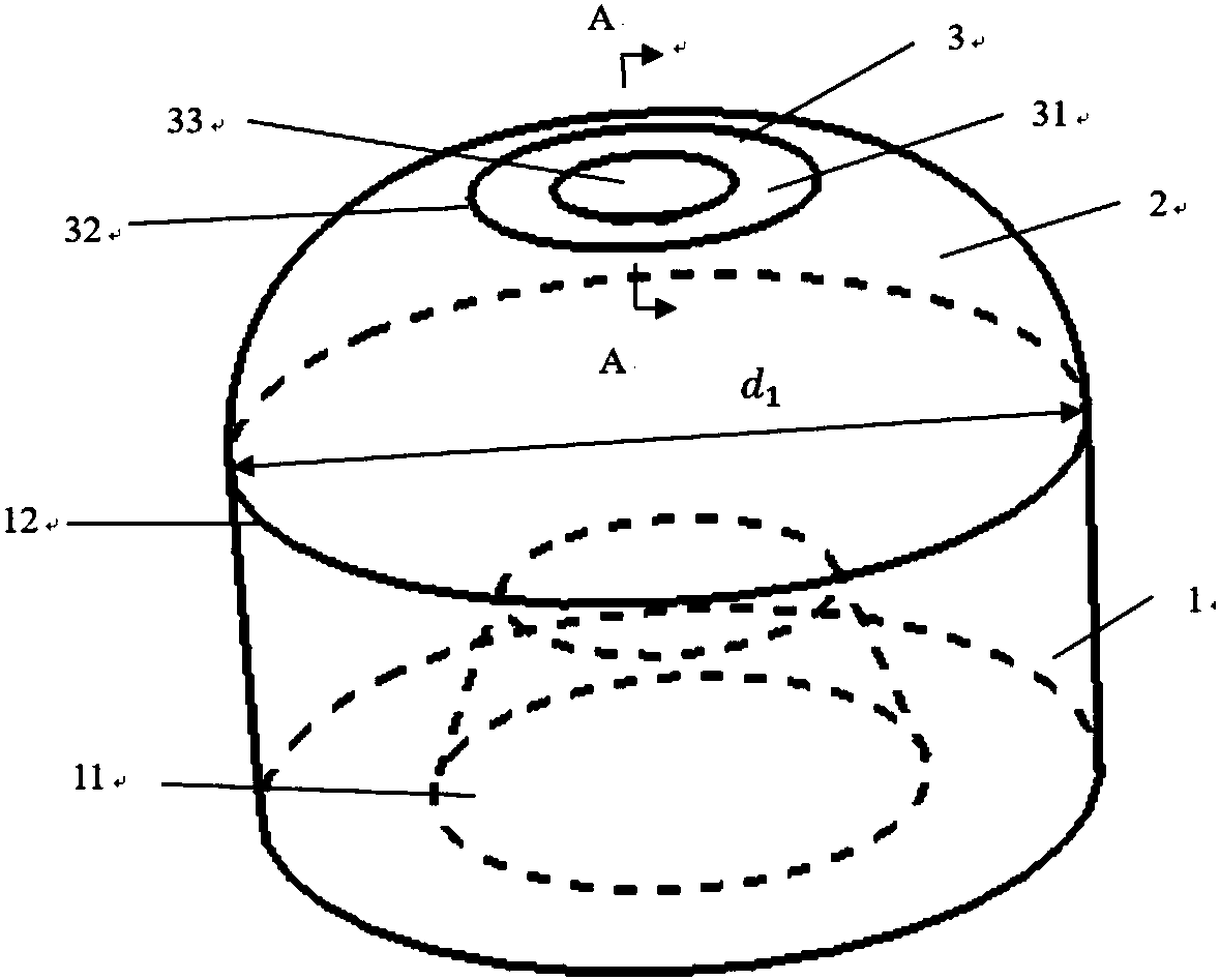
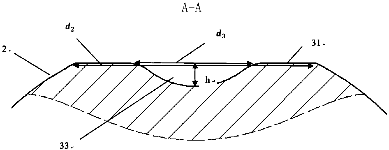
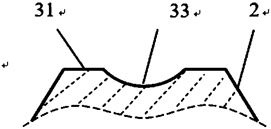
[0075] Such as Figure 1-2 As shown, the resistance spot welding electrode cap of this embodiment includes a substantially cylindrical electrode cap body 1 and a contact surface 3 between the electrode and the welding metal material. The body 1 has an electrode installation channel 11 at one end and a circumference 12 at the other end. The contact surface 3 includes a welding surface 31 , a circumference 32 and a groove 33 . The groove 33 is located in the central area of ​​the contact surface 3 .

[0076] One end of the body 1 refers to the end connected to the resistance spot welding machine during resistance spot welding, and the other end refers to the end close to the contact surface of the welding workpiece.

[0077] In another preferred example, the shape of the electrode installation channel 11 is a truncated cone or a cylinder, and the shape of the electrode installation channel 11 may also be some other appropriate shapes.

[0078] The circle 32 is parallel to the...

Embodiment 2

[0088] The resistance spot welding electrode cap of the present embodiment is similar to Embodiment 1, and the difference is that there is a raised annular ridge 4 on the welding surface 31 or the groove 33 of the present embodiment, as Figure 15-16 As shown, the annular ridge 4 includes an inner annular ridge 41 , an outer annular ridge 42 and grooves 43 formed at intervals between different annular ridges. The annular ridge 4 can be understood as a cross-section 44 is a circular structure formed by rotating a plane with a certain structure around the central axis of the electrode cap, wherein the lower part of the cross-section 44 is in contact with the welding surface 31, and the entire cross-section 44 is in contact with the welding surface 31. The welding surfaces 31 are vertical. The central axis of the electrode cap is a straight line passing through the center of the circle 12 and perpendicular to the circle 12 . It should be noted that the number of the annular ridg...

Embodiment 3

[0093] This embodiment discloses the device and process of welding aluminum alloy workpieces using the electrode cap of the present invention, such as Figure 36 As shown, 5 is a welding torch that can be used for resistance spot welding to connect the welding position 8 of the first aluminum alloy workpiece 6 and the second aluminum alloy workpiece 7, and the welding torch 5 includes a first welding torch arm 51, a second welding torch arm 52, a first welding torch An electrode cap 53 and a second welding electrode cap 54 . The first and second aluminum alloy workpieces 6 and 7 are made of aluminum alloy such as aluminum-magnesium alloy, aluminum-silicon alloy, aluminum-magnesium-silicon alloy or aluminum-copper alloy, and the thickness of the aluminum alloy workpiece is 0.5-3mm. More preferably, the aluminum alloy workpiece can be 2.0mm thick 5182-O aluminum alloy. During welding, there can be two aluminum alloy workpieces (such as only 6 and 7) or a combination of more tha...


PUM

PropertyMeasurementUnit
depthaaaaaaaaaa
radiusaaaaaaaaaa
thicknessaaaaaaaaaa

Abstract

The invention discloses a resistance spot welding electrode cap. A groove is formed in the center of a welding contact surface of the electrode cap; in the welding process, the contact area between the electrode cap and a to-be-welded metal workpiece is reduced due to the existence of the groove; in the initial stage, overall produced heat is concentrated to outer rings of welding spots, so that the heat dissipation speed is low, and formation of molten cores from outside to insideis facilitated; and due to the existence of the groove, the metal workpiece expands towards the sunk part of the center of an electrode, the molten cores of the welding spots areincreased, and splashing and deforming are reduced. Compared with a traditional electrode cap, the welding current needed for forming the welding spots inthe same size by the electrode capis lower, and the electric power cost is reduced; and when the same current is used, the strength and the stability of the obtained welding spots are higher, and the welding defects are fewer.

Description

technical field [0001] The invention relates to the field of resistance spot welding, in particular to a welding electrode cap used for resistance spot welding between two or more layers of metal workpieces. Background technique [0002] With the gradual aggravation of global warming and energy depletion, the exhaust emissions and energy consumption of automobiles are becoming more and more serious. Experiments have proved that the weight of automobiles will be reduced by half, and the fuel consumption will also be reduced by nearly half. Due to the needs of environmental protection and energy saving, the light weight of automobiles Quantification has become the trend of the world's automobile development. Since the aluminum alloy material has the advantages of high strength, light weight, excellent corrosion resistance, and is suitable for various forming methods, using aluminum alloy instead of steel plate material for welding can reduce the structural weight by more than ...

Claims


Application Information

Patent Timeline
Patent Type & Authority Applications(China)
IPC IPC(8): B23K11/30
CPCB23K11/30B23K11/3009B23K35/02B23K11/11B23K11/16B23K35/0205
Inventor 杨上陆王艳俊
Owner SHANGHAI INST OF OPTICS & FINE MECHANICS CHINESE ACAD OF SCI
Why Eureka
Try Eureka