Ignition and combustion device for natural gas reforming hydrogen generator

A technology for reforming a hydrogen production device and a combustion device, which is applied in the directions of gas fuel burners, burners, burners, etc., can solve the problems of incomplete combustion in the combustion chamber, unstable ignition state, and tempering of the combustion outer tube. The effect of complete and complete combustion, low manufacturing cost and stable combustion process

Active Publication Date: 2019-10-25
ZHANGJIAGANG RES INST OF HYDROGEN ENERGY CO LTD
View PDF12 Cites 0 Cited by
  • Summary
  • Abstract
  • Description
  • Claims
  • Application Information

AI Technical Summary

Problems solved by technology

[0004] 1. The ignition state of this structure is unstable. When the gap between the ignition electrodes does not meet the design requirements or carbon deposits occur at the end of the ignition rod, it will lead to failure to ignite and burn;
[0005] 2. The structure uses the upper part of the combustion chamber to ignite, which may easily lead to incomplete combustion in the combustion chamber;
[0006] 3. After the structure is ignited and burned, the combustion chamber is flaming combustion, and the highest point of the flame combustion temperature is around the flame. Since the flame is in the upper part of the combustion chamber and is relatively close to the stabilizing plate, it is very easy to backfire in the combustion outer tube. cause safety accident

Method used


Image

  • Ignition and combustion device for natural gas reforming hydrogen generator
  • Ignition and combustion device for natural gas reforming hydrogen generator
  • Ignition and combustion device for natural gas reforming hydrogen generator

Examples


Embodiment 1

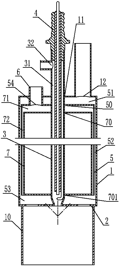
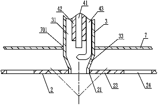
[0023] Such as figure 1 and image 3 As shown, the ignition and combustion device of a natural gas reforming hydrogen production device described in this embodiment includes: an outer cylinder body 1 with a closed top end and an open bottom end, and a combustion stabilizing sheet 2 sealed at the bottom end of the outer cylinder body 1, Make the inner cavity of the outer cylindrical body 1 form a closed cavity. In the middle of the combustion stabilizing sheet 2, there is a through-hole 21 that penetrates up and down. The bottom end of the combustion outer tube 3 seals and passes through the first through-hole 11 in the middle of the top end of the outer cylinder 1 and then is sealed and connected with the through-hole 21. The top end of the combustion outer tube 3 is upward. Stretch out of the outer cylinder 1. The ignition combustion device is arranged at the gas inlet of the combustion chamber 10 of the natural gas reforming hydrogen production device, and the combustion s...

Embodiment 2

[0030] see figure 1 As shown, the difference between this embodiment and the first embodiment is that: the second mixed gas inlet 12 is opened at the top of the outer cylinder 1 . A first cylinder 5 is arranged in the inner cavity of the outer cylinder 1, the top and bottom of the first cylinder 5 are closed, a second through hole 50 is opened in the middle of the top of the first cylinder 5, and a second through hole 50 is opened at the bottom of the first cylinder. A connection through hole is opened in the middle, and the first cylinder 5 is sleeved and fixed on the combustion outer tube 3 through the second through hole 50 and the connection through hole, and the outer wall of the first cylinder 5 and the inner wall of the outer cylinder 1 The interlayer forms the gas mixture channel 52 , the gap between the top of the first cylinder 5 and the top of the outer cylinder 1 forms the first cavity 51 , and the gap between the bottom of the first cylinder 5 and the combustion s...

Embodiment 3

[0038] like figure 1 As shown, the difference between this embodiment and the first embodiment is that: the second mixed gas inlet 12 is opened at the top of the outer cylinder 1 . A first cylindrical body 5 is arranged in the inner cavity of the outer cylindrical body 1. The top end of the first cylindrical body 5 is closed and the bottom end is open. A second through hole 50 is opened in the middle of the top end of the first cylindrical body 5. At the bottom end of the first cylindrical body A connection through hole is opened in the middle, and the first cylinder 5 is sleeved and fixed on the combustion outer tube 3 through the second through hole 50 and the connection through hole, and the outer wall of the first cylinder 5 and the inner wall of the outer cylinder 1 The interlayer forms the gas mixture channel 52 , and the gap between the top end of the first cylinder body 5 and the top end of the outer cylinder body 1 forms the first cavity 51 .

[0039] A waste gas inl...


PUM

PropertyMeasurementUnit
heightaaaaaaaaaa

Abstract

The invention discloses an ignition and combustion device for a natural gas reforming hydrogen generator. The ignition and combustion device comprises an outer cylinder body with a sealed top end, wherein a stable combustion sheet covers the position of the opening of the bottom end of the outer cylinder body in a sealed manner; the bottom end of a combustion outer tube penetrates through a firstthrough hole located at the central part of the top end of the outer cylinder body in a sealed manner and is in sealed connection with the through hole located at the central part of the stable combustion sheet; an ignition electrode ceramic tube with an ignition electrode wire is connected with an ignition rod to constitute an integral ignition rod; the upper part of the ignition rod is fixedly provided with a locking nut; the top part of the combustion outer tube is provided with a threaded section matching with the locking nut; the ignition rod extends into the tube chamber of the combustion outer tube and is fixedly arranged in the tube chamber of the combustion outer tube through threaded engagement of the locking nut with the threaded section; a first mixed gas inlet is arranged on the wall of the combustion outer tube located outside of the outer cylinder body; a second mixed gas inlet is arranged on the outer cylinder body; a mixed gas channel communicating with the second mixed gas inlet is also arranged in the outer cylinder body; and a plurality of jet holes are arranged on the stable combustion sheet. The device provided by the invention has the advantages of high safety performance, long service life and high combustion efficiency.

Description

technical field [0001] The invention relates to the technical field of hydrogen production by reforming natural gas, in particular to an ignition combustion device of a hydrogen production device by reforming natural gas. Background technique [0002] Due to its advantages of high efficiency, cleanliness, and safety, hydrogen energy is regarded as the most promising clean energy in the 21st century. At present, hydrogen production mainly includes three ways: natural gas reforming hydrogen production, electrolytic water hydrogen production and industrial by-product hydrogen. Among them, the main reaction of natural gas reforming to produce hydrogen is the conversion reaction of methane and steam. The conversion reaction is a strong endothermic reaction with a high enthalpy value. During the reaction, the system temperature is 600°C-800°C and the pressure is 25×10 5 Pa~35×10 5 Pa, so it is necessary to burn natural gas inside the natural gas reforming hydrogen production uni...

Claims


Application Information

Patent Timeline
Patent Type & Authority Applications(China)
IPC IPC(8): C01B3/34F23D14/02F23D14/26F23D14/60F23D14/62
CPCC01B3/34F23D14/02F23D14/26F23D14/60F23D14/62C01B2203/0205F23D2207/00
Inventor 苏红艳丁桓展王学圣唐健赵亚丽倪中华严岩崔鸿
Owner ZHANGJIAGANG RES INST OF HYDROGEN ENERGY CO LTD
Why Eureka
Try Eureka