
Closed-loop fiber gyro signal modulation method

A fiber optic gyroscope and signal modulation technology, which is applied in Sagnac effect gyroscopes, gyroscopes/steering sensing equipment, instruments, etc., can solve the problem of fiber optic gyroscope noise characteristics, dead zone characteristics, scale factor nonlinearity degradation, modulation Frequency alignment error and other issues, to achieve high dynamic tracking performance and good real-time performance

Active Publication Date: 2019-10-25
HUNAN AEROSPACE ELECTROMECHANICAL EQUIP & SPECIAL MATERIAL INST
View PDF7 Cites 7 Cited by
  • Summary
  • Abstract
  • Description
  • Claims
  • Application Information

AI Technical Summary

Problems solved by technology

In the temperature environment, the expansion and contraction of the fiber optic ring and the change of the optical refractive index will cause the eigenfrequency of the fiber optic gyroscope to change, resulting in an alignment error between the eigenfrequency of the fiber optic gyroscope and the modulation frequency of the gyroscope, which in turn leads to "spikes" in the detector signal. "The change of the signal causes the zero offset drift of the fiber optic gyroscope, which leads to the deterioration of the noise characteristics, dead zone characteristics and small signal non-linear characteristics of the fiber optic gyroscope. This effect is especially obvious in high-precision fiber optic gyroscopes.
[0005] The eigenfrequency of the fiber optic gyroscope is the frequency corresponding to the transmission time of the optical signal in the Sagnac sensitive loop. Since the eigenfrequency will drift with the change of temperature, the traditional four-state square wave modulation method cannot track the eigenfrequency Frequency dynamically adjusts the modulation frequency

Method used


Image

  • Closed-loop fiber gyro signal modulation method
  • Closed-loop fiber gyro signal modulation method
  • Closed-loop fiber gyro signal modulation method

Examples


Embodiment Construction

[0029] The technical solutions in the present invention are clearly and completely described below in combination with the accompanying drawings in the embodiments of the present invention. Obviously, the described embodiments are only some of the embodiments of the present invention, not all of them. Based on the embodiments of the present invention, all other embodiments obtained by persons of ordinary skill in the art without making creative efforts belong to the protection scope of the present invention.

[0030] A kind of closed-loop fiber optic gyroscope signal modulation method provided by the present invention comprises the following steps:

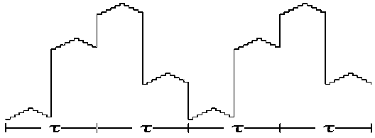
[0031] Step (1) The FPGA of the fiber optic gyroscope generates a four-state square wave modulation signal with a time period of 2τ and a height of k1, such as figure 1 shown.

[0032] In this embodiment, the time period τ is determined by measuring the output signal of the photodetector with an oscilloscope, and the time period ...


PUM


Abstract

The invention discloses a closed-loop fiber gyro signal modulation method, and relates to the technical field of fiber gyro signal modulation and demodulation. According to the modulation method, themodulation frequency of a fiber gyro is dynamically adjusted via a four-mode square wave modulation signal plus a sawtooth step modulation signal, an error is resolved and real-time fed back within each tau / 2 period, new modulation frequency is generated on such basis, the modulation frequency is dynamically adjusted in a next tau period, and the intrinsic frequency is tracked and the modulation frequency is rapidly and dynamically adjusted in the next tau period. The modulation frequency is dynamically adjusted via existing circuits and optical paths, intrinsic frequency tracking data is completely synchronized with fiber gyro signal processing data, there is no problems in delay and data synchronization among the signals, the instantaneity is high, use is simple and convenient, the dynamic tracking performance is higher, and extra parts are not needed.

Description

technical field [0001] The invention belongs to the field of signal modulation and demodulation of an optical fiber gyroscope, in particular to a closed-loop optical fiber gyroscope signal modulation method. Background technique [0002] Fiber optic gyroscope is a sensor sensitive to angular rate and angular deviation based on the Sagnac effect. Different from traditional mechanical gyroscopes, fiber optic gyroscopes get rid of the category of rotor gyroscopes, without mechanical transmission parts, and without friction It has the characteristics of long life, light weight, small size, low power consumption, large measurement range, quick startup, and flexible structural design. Due to its potential accuracy, fiber optic gyroscopes have replaced most of the traditional mechanical gyroscopes in sea, land, air, and space applications, and have played a key role. [0003] The optical power response of the fiber optic gyro is the cosine function of the Sagnac phase difference c...

Claims


Application Information

Patent Timeline
IPC IPC(8): G01C19/72
CPCG01C19/721
Inventor 刘智荣
Owner HUNAN AEROSPACE ELECTROMECHANICAL EQUIP & SPECIAL MATERIAL INST
Learn More