Miniaturized multiband common-aperture circularly polarized antenna

A circularly polarized antenna, common aperture technology, applied in antennas, antenna arrays, antenna grounding devices, etc., can solve the problems of increased antenna gain, narrowed beam, and rapid gain drop, reducing overall height and manufacturing costs. , the effect of reducing complexity

Active Publication Date: 2019-10-25
XIDIAN UNIV
View PDF8 Cites 8 Cited by
  • Summary
  • Abstract
  • Description
  • Claims
  • Application Information

AI Technical Summary

Problems solved by technology

Nowadays, omnidirectional circularly polarized antennas are easily affected by the structure of the carrier and occupy a large volume
[0004] To sum up, the problems existing in the existing technology are: limited carrier space, antenna impedance matching after miniaturization; dual circularly polarized The shape and size of the space, the low profile and conformal design of the omnidirectional circularly polarized antenna, the impedance and pattern of the antenna are easily affected by the carrier; multiple wide bandwidth angles cover dual circularly polarized antennas and omnidirectional circularly polarized antennas When the common aperture is placed, the mutual influence between the antennas and other issues
[0005] The difficulty of solving the above technical problems: the height of the Vivaldi antenna is usually between λ/2 and λ. Due to the limited space, when the height is reduc

Method used


Image

  • Miniaturized multiband common-aperture circularly polarized antenna
  • Miniaturized multiband common-aperture circularly polarized antenna
  • Miniaturized multiband common-aperture circularly polarized antenna

Examples


Embodiment Construction

[0039] In order to make the object, technical solution and advantages of the present invention more clear, the present invention will be further described in detail below in conjunction with the examples. It should be understood that the specific embodiments described here are only used to explain the present invention, not to limit the present invention.

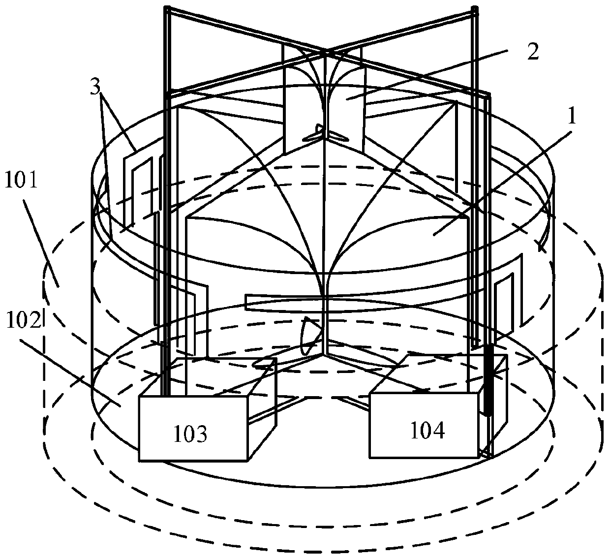
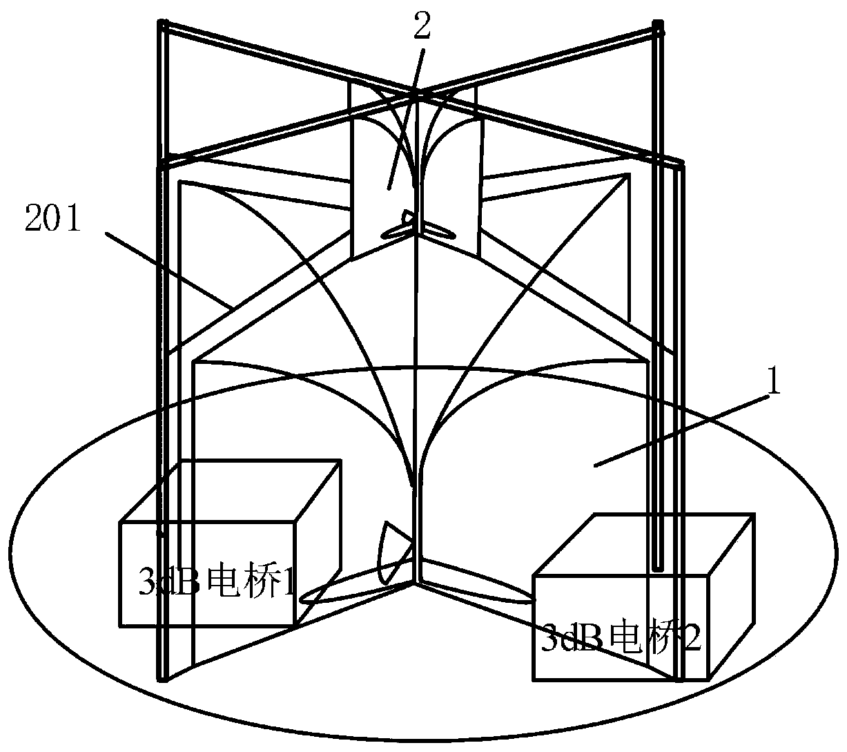
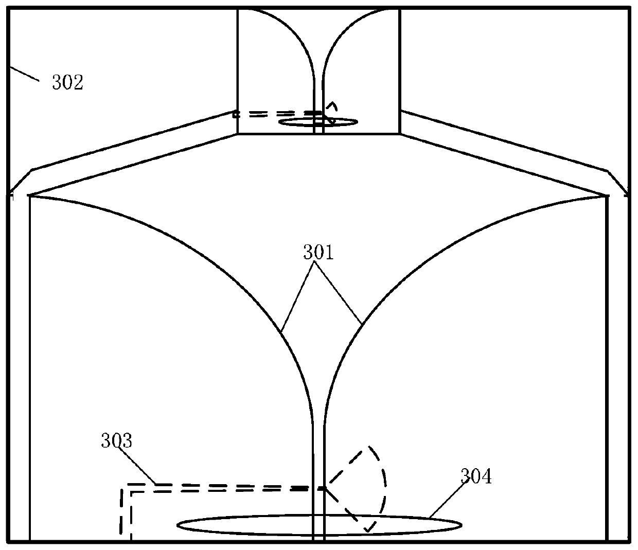
[0040] For dual circularly polarized antennas, it is necessary to satisfy both wide-angle gain coverage and broadband operation; use the shape and space size of the carrier, conformal design of omnidirectional circularly polarized antennas; multiple wide-bandwidth angles cover dual circularly polarized and omnidirectional Circularly polarized antenna common aperture and other issues. The three antennas of the present invention are all in the form of printed medium substrates, which reduces the complexity and manufacturing cost of the antennas. The three circularly polarized antennas can be independent of each other and do ...


PUM

PropertyMeasurementUnit
Thicknessaaaaaaaaaa
Thicknessaaaaaaaaaa

Abstract

The invention belongs to the technical field of wireless communication, and discloses a miniaturized multiband common-aperture circularly polarized antenna. The antenna is provided with three antennas, a metal back cavity, a metal bottom plate, a strip line power division network and two 3dB directional couplers, wherein an X-band dual circularly polarized antenna is located on the upper layer, the SC-band dual circularly polarized antenna is located on the lower layer, and the L-band omnidirectional circularly polarized antenna clings to the inner side of the metal back cavity; the metal backcavity and the three circularly polarized antennas are coaxially arranged; a strip line power division network and two 3dB directional couplers are arranged on the inner side of the metal back cavity. The two broadband wide-angle coverage dual circularly polarized antennas both use a crossed Vivaldi antenna, and dual circular polarization is realized through the 3dB directional couplers. According to the invention, the omnidirectional circularly polarized antenna employs four identical inverted F antennas which are connected through an equal power division strip line network. The antenna is compact in structure and simple in manufacturing process, the three antennas are independent of one another and do not influence one another, and multi-band common-aperture work is achieved.

Description

technical field [0001] The invention belongs to the technical field of wireless communication, in particular to a miniaturized multi-band common-aperture circularly polarized antenna. Background technique [0002] Compared with linearly polarized antennas, circularly polarized antennas have their natural advantages. Not only has polarization matching characteristics, but also can suppress the interference of reflected clutter such as rain and fog, has strong anti-interference ability, and is beneficial to the reception of electromagnetic waves in space. The dual circularly polarized antenna can transmit or receive electromagnetic waves of two directions in the same frequency band, which can realize the functions of two antennas and reduce the complexity of the antenna and the installation space of the antenna. In order to ensure normal communication, a certain gain is usually required at low elevation angles. It is difficult to realize that the antenna can work in a wide f...

Claims


Application Information

Patent Timeline
IPC IPC(8): H01Q1/36H01Q1/38H01Q1/48H01Q1/50H01Q15/24H01Q21/00H01Q21/30
CPCH01Q1/36H01Q1/38H01Q1/48H01Q1/50H01Q15/24H01Q21/0006H01Q21/30
Inventor 胡代松陈曦付桂林傅光
Owner XIDIAN UNIV
Why Eureka
Try Eureka