Buoyancy kinetic energy power generation device
A power generating device and a technology of a generating device, which are applied in the field of buoyancy power generation devices and buoyancy power generation, can solve the problems of no practical value, lack of technical feasibility and practical application value, etc.
- Summary
- Abstract
- Description
- Claims
- Application Information
AI Technical Summary
Problems solved by technology
Method used
Image
Examples
Embodiment 1
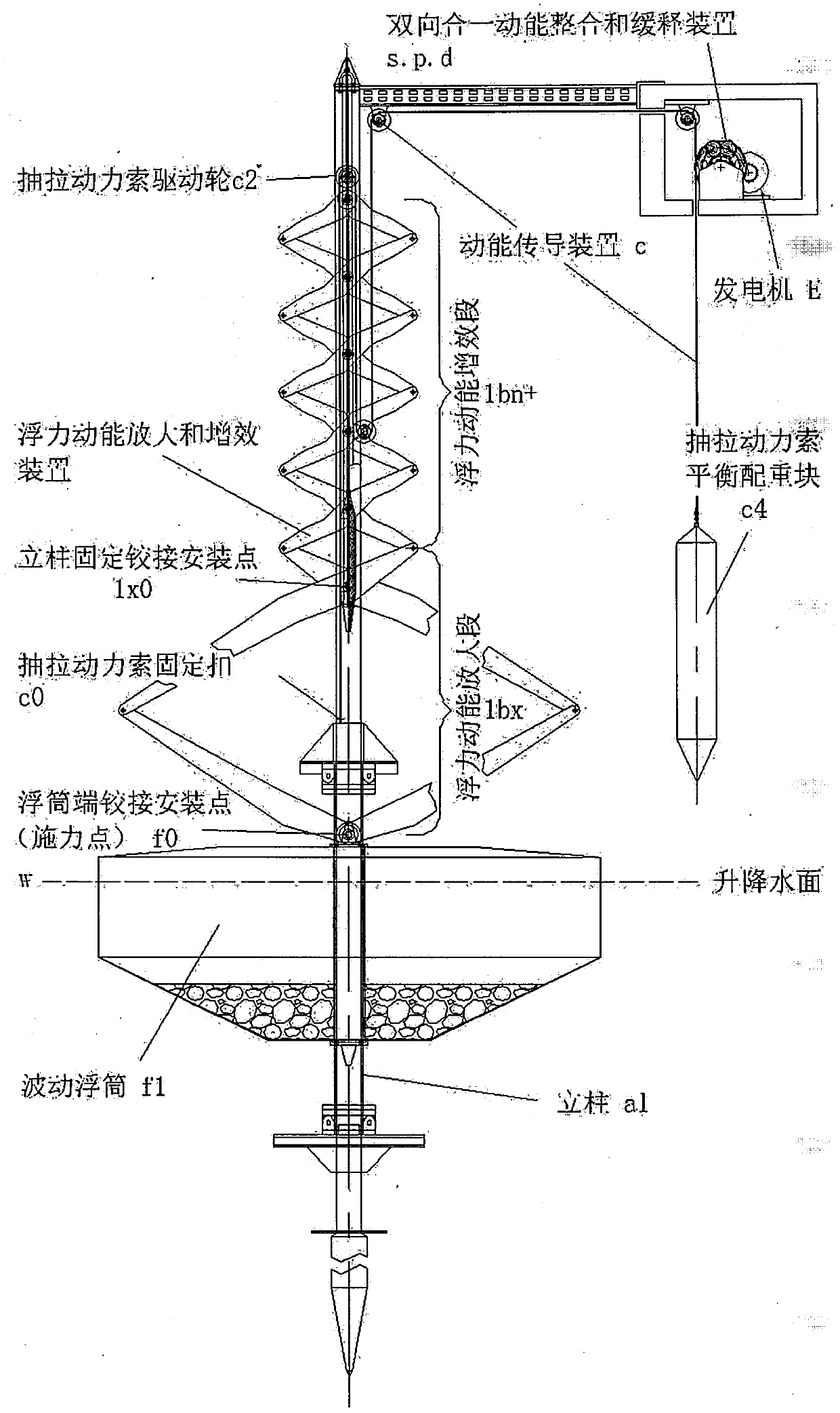
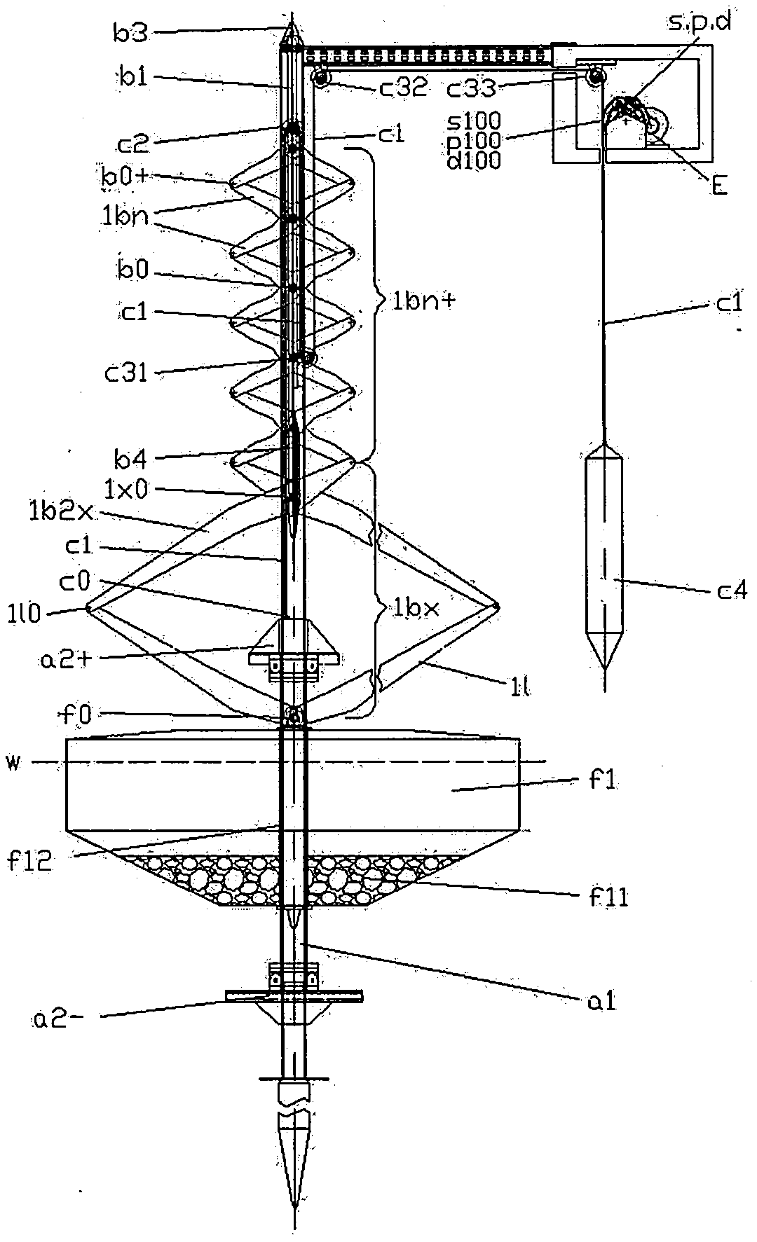
[0062] A buoyancy power generation device for cascaded water level lifting pools (see Figure 08) set by using the constant flow of mountain streams, consisting of a buoyancy kinetic energy generating device, a buoyancy kinetic energy amplification and synergizing device, a kinetic energy transmission device, and a two-way integrated kinetic energy integration and slow release device ( See Fig. 01). The buoyancy kinetic energy generating device is composed of a positioning column a1 and a wave buoy f1; the wave buoy f1 is half-floating on the water surface, and the bottom of the wave buoy f1 is provided with a buoy counterweight f11, and its central symmetrical position is provided with two vertically juxtaposed The central lumen f12 of the upright column, the upright column a1 slides and fits in the central lumen f12 of the upright column and runs through it, and the buoy end hinged installation point f0 is set at the top center of the wave buoy f1; the buoyancy kinetic energy ...
Embodiment 2
[0071] A buoyancy power generation device (see Fig. 09 and 10) set by using the general drop water level of the river, which is composed of a buoyancy kinetic energy generating device, a buoyancy kinetic energy amplification and synergizing device, a kinetic energy transmission device, a two-way integrated kinetic energy integration and a slow release device ( See Fig. 01).
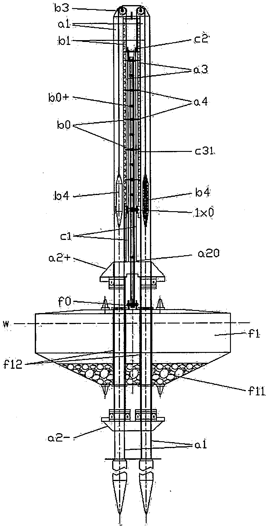
[0072] The buoyancy kinetic energy generating device is composed of a positioning column a1 and a wave buoy f1; the wave buoy f1 is half-floating on the water surface, and the bottom of the wave buoy f1 is provided with a buoy counterweight f11, and its central symmetrical position is provided with two vertically juxtaposed The central lumen f12 of the upright column, the upright column a1 slides and fits in the central lumen f12 of the upright column and runs through it, and the buoy end hinged installation point f0 is set at the top center of the wave buoy f1; the buoyancy kinetic energy amplification an...
Embodiment 3
[0083] A sea-based moored chain positioning and depth-fixed suspension platform type buoyancy power generation device (see Figure 11 ), consisting of buoyancy kinetic energy generating device, buoyancy kinetic energy amplification and synergizing device, kinetic energy transmission device, two-way integrated kinetic energy integration and slow release device (see Figure 01). The buoyancy kinetic energy generating device is composed of a positioning column a1 and a wave buoy f1; the wave buoy f1 is half-floating on the water surface, and the bottom of the wave buoy f1 is provided with a buoy counterweight f11, and its central symmetrical position is provided with two vertically juxtaposed The central lumen f12 of the upright column, the upright column a1 slides and fits in the central lumen f12 of the upright column and runs through it, and the buoy end hinged installation point f0 is set at the top center of the wave buoy f1; the buoyancy kinetic energy amplification and syner...
PUM
 Abstract
Description
Claims
Application Information
 - R&D
- Intellectual Property
- Life Sciences
- Materials
- Tech Scout
- Unparalleled Data Quality
- Higher Quality Content
- 60% Fewer Hallucinations
Browse by: Latest US Patents, China's latest patents, Technical Efficacy Thesaurus, Application Domain, Technology Topic, Popular Technical Reports.
© 2025 PatSnap. All rights reserved.Legal|Privacy policy|Modern Slavery Act Transparency Statement|Sitemap|About US| Contact US: help@patsnap.com


