Flight path planning method for coordinated detection and obstacle avoidance of unmanned aerial vehicle group

A track planning and unmanned aerial vehicle technology, applied in the field of unmanned aerial vehicles, can solve the problems of energy difference in optimization, failure to consider the turning radius of the drone, and failure to consider the impact, etc.

Active Publication Date: 2019-11-01
XIDIAN UNIV
View PDF8 Cites 25 Cited by
  • Summary
  • Abstract
  • Description
  • Claims
  • Application Information

AI Technical Summary

Problems solved by technology

[0003] The coordination mechanism of multiple UAVs is mainly to enable multiple UAVs to cooperate to complete the detection coverage of the warning area and avoid dangerous obstacles. At present, there are few studies on the area coverage of UAVs at home and abroad. Research on UAV area coverage. For example, in 2006, Agarwal's research adopted the idea of ​​​​area division, dividing the flight area into many rectangular sub-areas, and assigning areas according to the ability of each UAV to perform coverage tasks. The man-machine is simplified to only allow 90° and 180° turns, but this coverage scheme does not take into account the turning radius of the UAV; in 2010, Chen Hai et al. proposed a trajectory planning algorithm for convex polygonal areas , the problem of covering track planning in a convex polygon area is transformed into the problem of finding the width of a convex polygon. The UAV only needs to fly a "Z"-shaped route along the direction of the supporting parallel line when the width appears, but it does not take into account the flight path The influence of the minimum turning radius of the UAV on the "Z"-shaped route during the process
Regarding the research of UAVs on avoiding obstacles, for example, in 2012, Dong S et al. used the Dijkstra algorithm to find the optimal track based on the Voronoi diagram, regarded the threat as a point, and selected the line between the threat points. The intersection point of the mid-perpendicular line is the track point. This method can ensure that the track is maximized to avoid various threats, and the security is high, but the track is long and does not consider the constraints of the maximum turning angle of the UAV. The track is not necessarily Flyable; in 2016, Maini P et al. used the Dijkstra algorithm to find the shortest track based on the visual graph, regarded each vertex of the polygonal obstacle as the track point, and established a turning angle constraint mechanism. The track obtained by this method is short , satisfying the maximum turning angle constraint of the UAV, but because the track is close to obstacles, the safety is low
[0004] The above methods of area coverage track planning are mostly aimed at the situation where the starting point and the end point of the required track are fixed, and the optimal track is formed by cutting the area, avoiding obstacles, constraining fuel consumption and the number of turns, so that a specific UAV The coverage of each area after cutting is achieved through the "cow plowing" flight route. These methods have certain defects. When planning the trajectory of a large-scale complex environment, the path search will cause excessive calculations, low efficiency, and Optimizing issues such as poor energy, so the efficiency and reliability of trajectory planning cannot be guaranteed
In addition, in actual situations, UAVs will be required to continuously and uninterruptedly monitor designated areas while avoiding obstacles and achieving maximum coverage. The trajectory planning required by such missions often does not have a fixed starting point and the end point, the above-mentioned trajectory planning methods cannot solve such problems

Method used


Image

  • Flight path planning method for coordinated detection and obstacle avoidance of unmanned aerial vehicle group
  • Flight path planning method for coordinated detection and obstacle avoidance of unmanned aerial vehicle group
  • Flight path planning method for coordinated detection and obstacle avoidance of unmanned aerial vehicle group

Examples


Embodiment 1

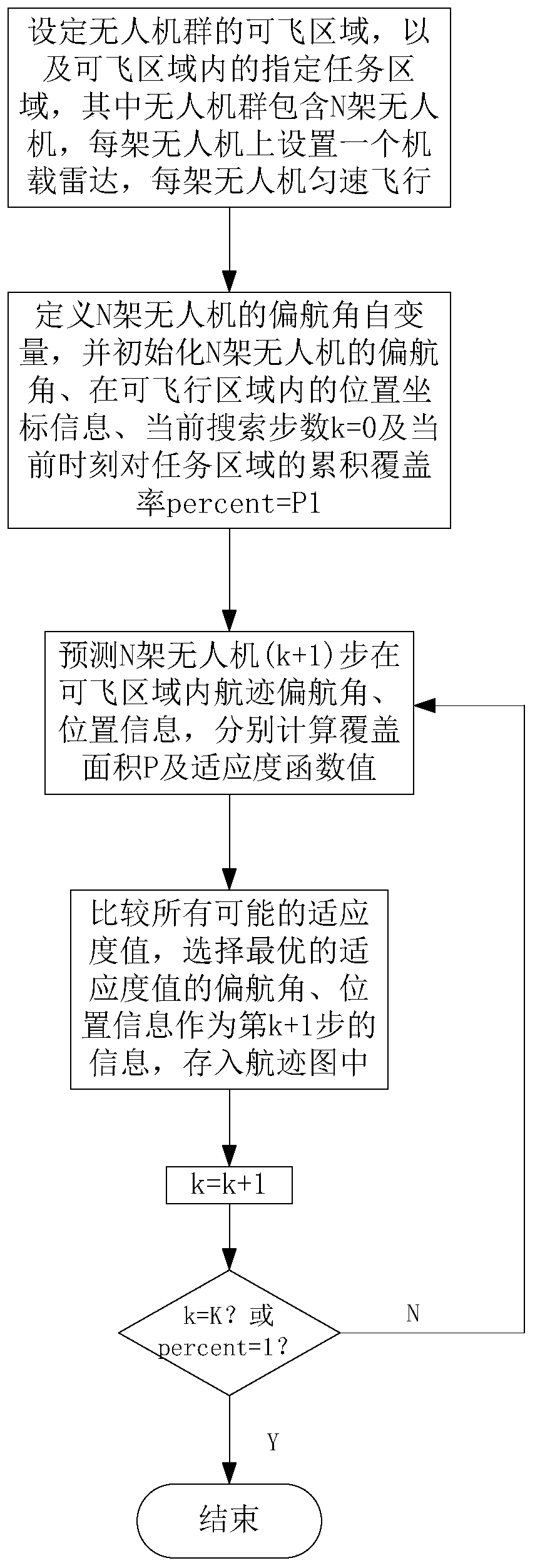
[0026] See figure 1 , figure 1 It is a flow chart of a UAV swarm cooperative detection and obstacle avoidance track planning method provided by an embodiment of the present invention. As shown in the figure, the track planning method of this embodiment includes:

[0027] S1: Set the flying area A of the UAV group, the designated task monitoring area S in the flying area A, and analyze the stress situation of the UAV at the same time, and divide the UAV within the maximum turning angle constraint The prediction target node of the next moment of the UAV, and calculate its node gain weight, the UAV group contains N UAVs, and an airborne radar is set on each UAV, and each UAV The machine flies at a constant speed;

[0028] Specifically, including:

[0029] S11: Setting the flyable area A of the drone swarm and the task monitoring area S, wherein, when the drone swarm performs a flight mission, the safe area where the drone swarm is allowed to fly is the flyable area A, the tas...

Embodiment 2

[0101] This embodiment provides a simulation experiment about the track planning method in Embodiment 1. In this embodiment, please refer to Table 1 for the simulation experiment conditions.

[0102] Table 1 Simulation experiment conditions

[0103]

[0104] See Figure 4 , Figure 4 It is a schematic diagram of the position of the unmanned aerial vehicle group at the initial moment in a simulation experiment provided by the embodiment of the present invention. As shown in the figure, the four symbols in the figure represent the unmanned aerial vehicles respectively. Please refer to Figure 5 with Image 6 , Figure 5 It is a simulation experiment provided by an embodiment of the present invention to obtain a flight path planning result map; Image 6 yes Figure 5 The enlarged view of the obstacle area in the middle, the different curves in the flyable area A in the figure represent the track planning trajectories of the four unmanned aerial vehicles respectively, it ...


PUM


Abstract

The invention relates to a flight path planning method for coordinated detection and obstacle avoidance of an unmanned aerial vehicle group. The method includes the following steps: S1. setting an unmanned aerial vehicle group flying area and designating a task monitoring area in the flying area; S2. defining yaw angle independent variables of N unmanned aerial vehicles, and initializing yaw angles, location coordinate information in the flying area, the number of current searching steps k=0, and the cumulative coverage percent=p1 on the task area at the current moment of the N unmanned aerialvehicles; S3. predicting flight path yaw angles and location information of (k+1) steps of the N unmanned aerial vehicles in the flying area, and separately calculating a coverage area and a fitnessfunction value; S4. comparing all possible fitness values, selecting a yaw angle and location information of an optimal fitness value as information of the (k+1)th step, and storing the yaw angle andthe location information in a flight path chart; and S5. enabling k=k+1, judging whether k=1 or percent=1, if yes, ending the planning, and otherwise, continuing S3 to S5. The method of the inventioncan realize the maximum monitoring coverage area, avoid obstacles and a required flight path has no fixed starting point and ending point.

Description

technical field [0001] The invention belongs to the technical field of unmanned aerial vehicles, and in particular relates to a track planning method for coordinated detection and obstacle avoidance of unmanned aerial vehicles. Background technique [0002] UAV combat has the advantages of small size, light weight, long battery life, strong load capacity, strong survivability, low cost, strong autonomous control ability, no casualties, and the ability to fly in high-risk airspace. However, the modern battlefield environment is complex and changeable, and has the characteristics of all-round and large depth. A single UAV is often unable to complete all air security tasks. The effectiveness of a UAV is very limited. Therefore, the cooperative operation of multiple drones can maximize the role of drones. [0003] The coordination mechanism of multiple UAVs is mainly to enable multiple UAVs to cooperate to complete the detection coverage of the warning area and avoid dangerous...

Claims


Application Information

Patent Timeline
Patent Type & Authority Applications(China)
IPC IPC(8): G05D1/10G01C21/20G01S13/93
CPCG01C21/20G05D1/104
Inventor 王彤王美凤乔格阁
Owner XIDIAN UNIV
Why Eureka
Try Eureka