Installation method for venting plugs for casting

An installation method and a technology for exhaust plugs, which are applied in casting and molding equipment, molds, molding machines, etc., can solve the problems that ordinary foundries cannot process by themselves, prolong the takt time of core grouping operations, waste man-hours and special glue, etc. The effect of shortening the takt time of core assembly, reducing the rate of trachoma and improving product quality

Inactive Publication Date: 2019-11-05
NANYANG FEILONG AUTOMOBILE PARTS CO LTD
View PDF4 Cites 0 Cited by
  • Summary
  • Abstract
  • Description
  • Claims
  • Application Information

AI Technical Summary

Problems solved by technology

[0002] The sand casting process is a casting method in which sand is used as the main molding material to prepare molds. It is also the most traditional casting method. Because sand casting is not limited by the shape, size, complexity and type of alloy of the parts, the production cycle is short and the cost is low. Low-level characteristics, sand casting is still the most widely used casting method in the foundry industry, especially suitable for single-piece or small-batch casting production; core assembly process, that is, to produce castings with core assembly technology, and the core assembly is composed of a single sand core. In the sand box of the molding line, because the sand core is filled with dried sand, the sand core is usually covered with a shell, and in order to prevent the box from expanding, running out of fire, and sand entering the cavity, the shell is usually used Screws are locked or sealed with sealing paste. In order to vent the sand core cavity, several vent holes are usually designed on the upper shell core. These vent holes need to be plugged with several vent plugs. The traditional method Firstly, the upper shell core is made by the core making method, and then the exhaust plugs are manually glued one by one to the places that need to be exhausted on the upper shell core. This method greatly prolongs the takt time of the core assembly operation. , often become the bottleneck of production capacity, and during the transfer process, the bonded exhaust plug is easy to fall off, resulting in a lot of sand in the cavity, trachoma waste, wasting a lot of man-hours and special glue, how to be more reliable and more Efficient installation of exhaust plugs has become a subject of core assembly work
[0003] The Chinese invention patent with the publication number CN105921695A discloses a vent plug and a casting process. One end of the main body of the vent plug is open, and a plurality of vent slots are provided at the other end. The opening is communicated with the vent hole of the mould, and a conical frustum is provided on the main body of the vent plug at one end of the vent groove. The direction is the same, and the above-described casting process is to set the exhaust plug on the vent hole in the mold of the sand core when the sand core is formed, and the sand core is formed at the corresponding position of the exhaust plug when the sand core is formed in the mold. An inverted circular cone hole, when the product is poured, the molten metal is close to the shape of the sand core to form a corresponding metal cone on the surface of the casting, so that the gas and impurities are concentrated at the metal cone, and the excess is cut from the product after molding metal cone, so as to reduce the impact of gas and impurities on the casting body, but the structure of the exhaust plug is relatively complicated, ordinary foundry factories cannot process it by themselves, and need to be customized separately, the processing cost is high, and the finished casting needs to be increased in the end. A step of cutting redundant metal cones, so the technical solution of the above invention cannot fully meet the requirements of further improving casting production efficiency and reducing production costs

Method used


Image

  • Installation method for venting plugs for casting
  • Installation method for venting plugs for casting
  • Installation method for venting plugs for casting

Examples


Embodiment Construction

[0018] The technical solutions of the present invention will be clearly and completely described below in conjunction with the accompanying drawings and specific embodiments. Apparently, the described embodiments are only part of the embodiments of the present invention, not all of them. Based on the embodiments of the present invention, all other embodiments obtained by persons of ordinary skill in the art without making creative efforts belong to the protection scope of the present invention.

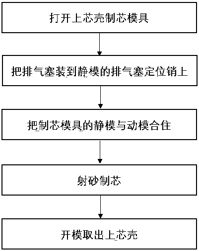
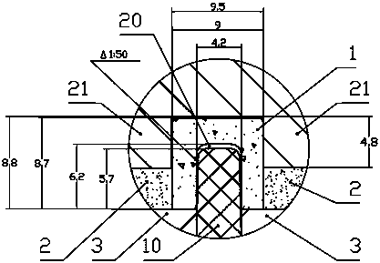
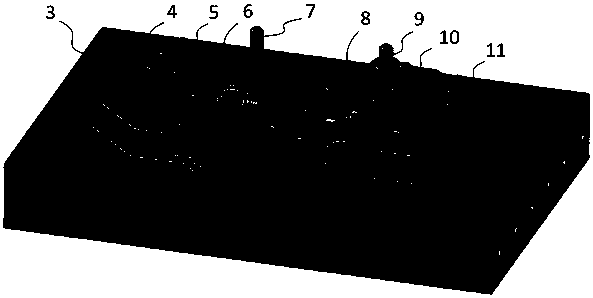
[0019] The casting of a turbine shell is made by a core assembly process. The core assembly process uses an upper shell core 2 and a lower shell core. Both the upper shell core 2 and the lower shell core are made by a core making process. shell core 2 is made of figure 2 The core-making mold shown is processed, and the cavity is mainly formed by buckling the static mold 3 and the movable mold 21; an exhaust plug g1 is provided at the position where exhaust is required, and the static...


PUM

PropertyMeasurementUnit
particle sizeaaaaaaaaaa
heightaaaaaaaaaa

Abstract

The invention discloses an installation method for venting plugs for casting. The venting plugs made from casting sand having sand particle sizes which are greater than the sand particle size of coresand for core making are used, and placed at corresponding positions in a die by virtue of an operation process of repairing each die by workers during production for a modelling line, and the ventingplugs are directly inlaid into the sand core in the process of core making, so that the previous operation method of needing to bond venting plugs one by one after core making is completed is avoided, the labor and glue water are saved, the core assembly rhythm is greatly shortened, and the bottleneck of capacity is broken through; and in addition, the previous phenomenon that the venting plugs are liable to separate off in a transfer process is further effectively prevented, so that the probability of sand entrance into a cavity is reduced, the sand-hole rejection rate of castings is lowered, and the product quality is effectively improved.

Description

technical field [0001] The invention belongs to the technical field of venting in the casting core making process, and in particular relates to a method for installing an exhaust plug of a sand core used for casting a turbine shell. Background technique [0002] The sand casting process is a casting method in which sand is used as the main molding material to prepare molds. It is also the most traditional casting method. Because sand casting is not limited by the shape, size, complexity and type of alloy of the parts, the production cycle is short and the cost is low. Low-level characteristics, sand casting is still the most widely used casting method in the foundry industry, especially suitable for single-piece or small-batch casting production; core assembly process, that is, to produce castings with core assembly technology, and the core assembly is composed of a single sand core. In the sand box of the molding line, because the sand core is filled with dried sand, the sa...

Claims


Application Information

Patent Timeline
Patent Type & Authority Applications(China)
IPC IPC(8): B22C15/24B22C9/10
CPCB22C9/106B22C15/24
Inventor 谢会豪刘松奇齐晓波彭德楼
Owner NANYANG FEILONG AUTOMOBILE PARTS CO LTD
Why Eureka
Try Eureka