
Mass production process suitable for plate welding receivers

A process and casing technology, which is applied in the field of mass production of plate welding casings, can solve the problems of insufficient control of the welding area of ​​the casing main body, difficulty in guaranteeing the dimensional accuracy of the casing main body, and high raw material procurement costs, and achieve a reduction of once The effect of reducing the amount of soldering, achieving mass production, and effective quality control

Active Publication Date: 2019-11-05
SICHUAN FUTURE AEROSPACE IND LLC
View PDF3 Cites 7 Cited by
  • Summary
  • Abstract
  • Description
  • Claims
  • Application Information

AI Technical Summary

Problems solved by technology

[0002] The aero-engine is the core component of the aircraft, and the casing is the key component of the aero-engine. It belongs to the typical thin-walled structure of the casing body, and its thinnest part is only 0.55mm. Processing materials, raw material procurement costs are extremely high, so it is particularly important to control the pass rate of the main body of the casing, but the conventional manufacturing process, the processing cycle is long, the main body of the casing is deformed, and the welding area of ​​the main body of the casing is often not well controlled, resulting in The dimensional accuracy of the main body of the casing is not easy to guarantee, thereby reducing the qualified rate of the main body of the casing

Method used


Image

  • Mass production process suitable for plate welding receivers
  • Mass production process suitable for plate welding receivers
  • Mass production process suitable for plate welding receivers

Examples


Embodiment 1

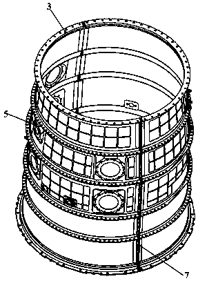
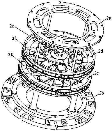
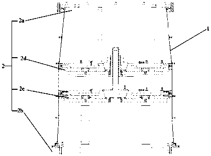
[0043] as attached figure 1 , attached figure 2 , attached image 3 , attached Figure 4 , attached Figure 5 And attached Image 6 In this embodiment shown, a mass production process suitable for plate welding receivers includes a receiver main body 1, a tooling I2, a top seat I2a, a base I2b, a lower positioning device I2c, an upper positioning device I2d, a driving device I2e, and a supporting member Ⅰ2f, flange side 3, tooling Ⅱ4, expansion core 41, mounting seat 5, tooling Ⅲ6, base Ⅲ6a, lower positioning device Ⅲ6b, upper locating device Ⅲ6c, support member Ⅲ6b1, driving device Ⅲ6d, longitudinal mounting edge 7, pick up the sheet And the flange side 3, according to the manufacturing process, the bent plate is blanked, and according to the welding process, the plate bent into a semi-conical structure is tailor-welded into several cones of different specifications, and the cones of different specifications are assembled and welded into the casing body 1 ;Use tooling I...


PUM


Abstract

The invention relates to the field of machinery, in particular to a mass production process suitable for plate welding receivers. During welding, a tool I is adopted to expand a receiver main body, sothat the outer surface of the receiver main body is bonded with the inner surface of a flange edge, the welding line quality is guaranteed, and the deformation of the receiver main body is the smallest; the end with the smaller diameter of the receiver main body is downwards; then, a tool II is lifted into the receiver main body from the top; the receiver main body and the tool II are totally heated according to a heat treatment process; the tool II drops to the bottom under the effect of gravity to achieve a shape correcting effect; when the receiver main body is machined, the receiver mainbody is clamped by adopting a tool III; the receiver main body and the flange edge are machined according to a manufacturing process, and a longitudinal mounting edge window is formed in the receivermain body; and the tool III is totally bonded with the inner wall of the receiver main body to prevent vibration of the receiver main body and cutter avoidance, so that the deformation of the receivermain body is reduced, the cutting parameters in the machining process can be doubled or higher, the machining period is shortened, and the mass production is realized.

Description

technical field [0001] The invention relates to the field of machinery, in particular to a mass production process suitable for plate welding casings. Background technique [0002] The aero-engine is the core component of the aircraft, and the casing is the key component of the aero-engine. It belongs to the typical thin-walled structure of the casing body, and its thinnest part is only 0.55mm. Processing materials, raw material procurement costs are extremely high, so it is particularly important to control the pass rate of the main body of the casing, but the conventional manufacturing process, the processing cycle is long, the main body of the casing is deformed, and the welding area of ​​the main body of the casing is often not well controlled, resulting in The dimensional accuracy of the main body of the casing is not easy to guarantee, thereby reducing the qualified rate of the main body of the casing. [0003] Therefore, a process is currently needed to shorten the p...

Claims


Application Information

Patent Timeline
IPC IPC(8): B23P15/00B23K37/04B23K31/02
CPCB23K31/02B23K37/04B23P15/00
Inventor 刘海波周超孟军
Owner SICHUAN FUTURE AEROSPACE IND LLC
Learn More