Rapid machining milling machine for key slot tool expanding and start-up based on wood mortise joint

A mortise joint and keyway technology, which is applied in the field of milling machines, can solve problems that affect the progress of the construction period, hidden dangers of industrial accidents, scratches on the arm, etc.

Active Publication Date: 2019-11-05
卢美华
View PDF8 Cites 3 Cited by
  • Summary
  • Abstract
  • Description
  • Claims
  • Application Information

AI Technical Summary

Problems solved by technology

[0004] Aiming at the deficiencies in the prior art, the purpose of the present invention is to provide a fast machining milling machine based on the key groove of wood tenon joint, so as to solve the different milling problems that require round chamfer and trapezoidal chamfer in the key groove of wood tenon joint. When the cutting tool is switched to the slotting process, the tool magazine of the milling machine often needs to stop suddenly and switch the tool holder within a period of time before continuing the tool processing. This will cause the round edge cutting wood marks to be covered by wood chips. There will be processing deviations, combined with artificial fan blowing out wood chips to press and push the machine head to adjust, it is more labor-intensive, and the manual pressure and push range will increase, vibrating the tool holder, which will easily cause the tool to loosen and slide, scratching the arm of the personnel, resulting in hidden dangers of industrial accidents. Insufficient continuous rapid processing of the keyway makes the wood processing process intermittent and slow, affecting the progress of the construction period

Method used


Image

  • Rapid machining milling machine for key slot tool expanding and start-up based on wood mortise joint
  • Rapid machining milling machine for key slot tool expanding and start-up based on wood mortise joint
  • Rapid machining milling machine for key slot tool expanding and start-up based on wood mortise joint

Examples


Embodiment Construction

[0030] In order to make the technical means, creative features, objectives and effects achieved by the present invention easy to understand, the present invention will be further explained below in conjunction with specific embodiments.

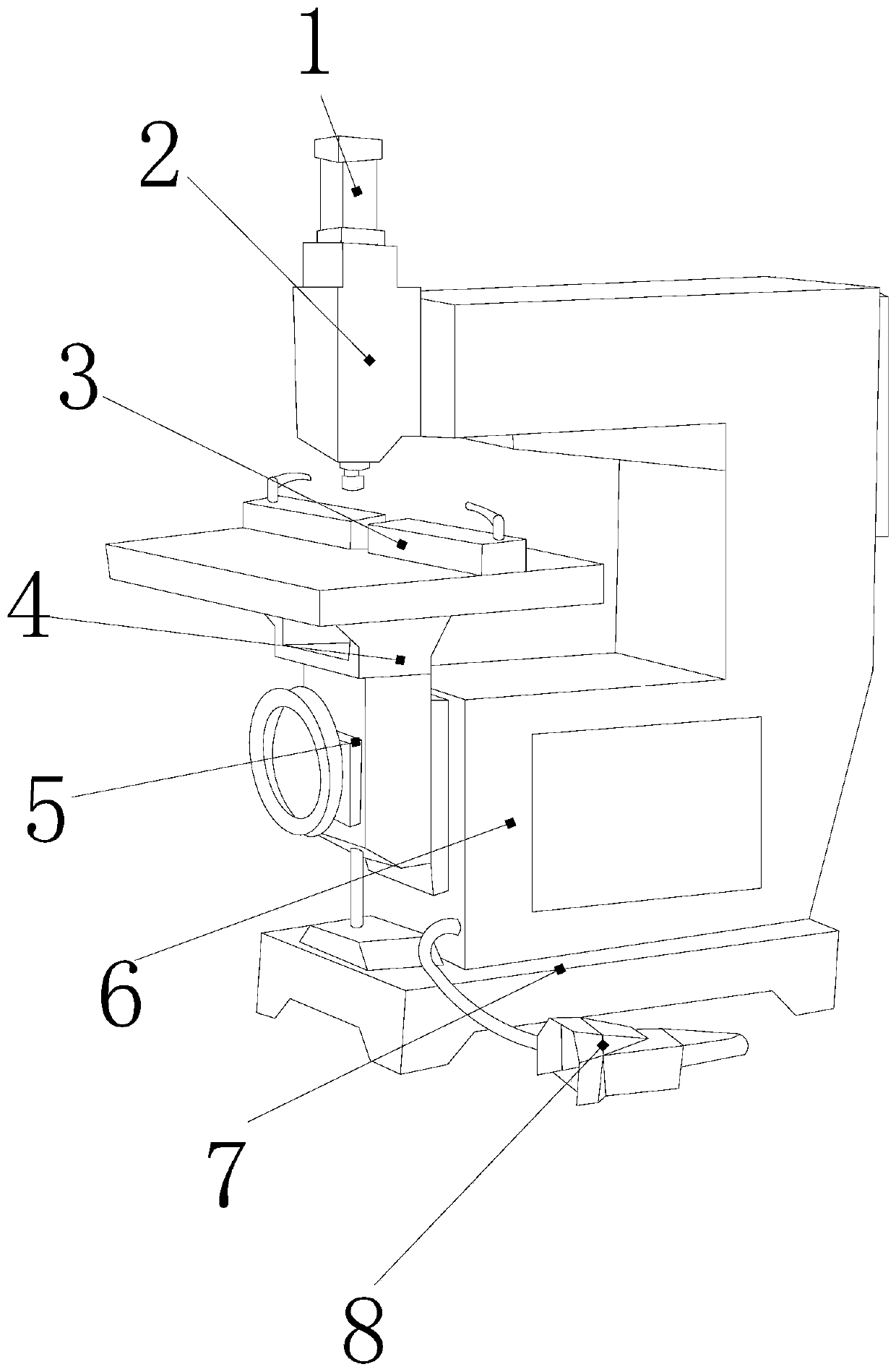
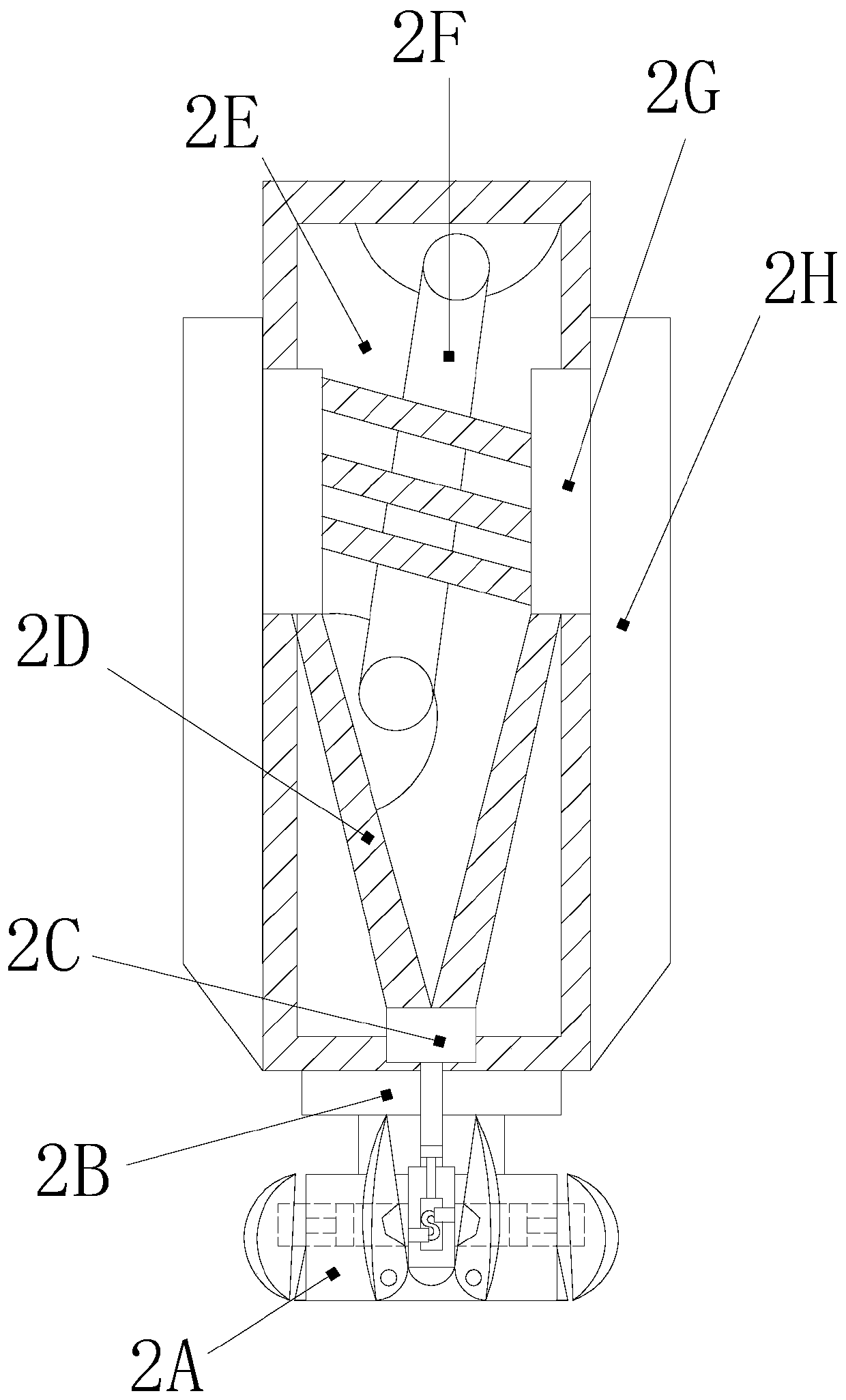
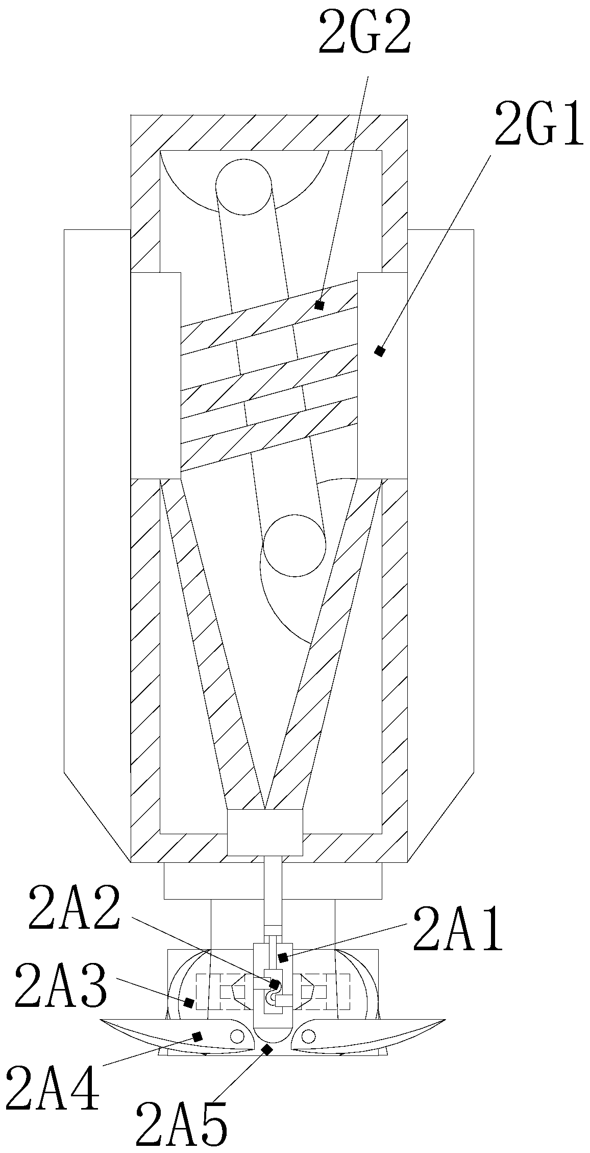
[0031] See Figure 1-Figure 7 , The present invention provides a rapid machining milling machine based on wood tenon joint keyway spreading knife punching, and its structure includes: axis motor 1, milling cutter shearing frame 2, clamping stage 3, concave bracket seat 4 , The roulette lifting column 5, the arm support block 6, the base plate 7, the power distribution plug 8, the milling cutter shearing frame 2 is nested under the bottom of the shaft motor 1, the milling cutter shearing machine The frame 2 is closely attached to the upper left corner of the arm support block 6, the arm support block 6 is welded on the top surface of the base plate 7, and the power distribution plug 8 is electrically connected to the electric board inside the arm...


PUM


Abstract

The invention discloses a rapid machining milling machine for key slot tool expanding and start-up based on wood mortise joint. The rapid machining milling machine structurally comprises a shaft driving motor, a milling tool shear rack, a clamping buckle carrying table, a concave bracket seat, a wheel disc lifting column, a holding arm support block, a base plate and a power distribution plug. According to the rapid machining milling machine, the milling tool shear rack is matched with the clamping buckle carrying table, seamless-splicing rotation layer tool expanding deformation effect is formed at the position, on the top of the clamping buckle carrying table, of an expanding variable tool rest body, the flexible shear effect of the short-time two-pole magnetic valve core rotary linkagetool releasing and tool retracting on continuous splicing processing of round chamfer and trapezoid chamfer on the wood is achieved, and it is ensured that a tool magazine is concentrated at the tailend of the bottom of the processing rack; and the single end head is in a changeable tool type, the layer-by-layer locking effect of the anti-skid tool is achieved, the personal safety of operators is guaranteed, the uninterrupted continuous reinforcement processing effect of cutting wood marks is optimized, and accurate and efficient processing processes with time shortened are brought to the wood key slots.

Description

Technical field [0001] The invention is a fast processing milling machine based on wood tenoning keyway spreading knife punching, belonging to the field of milling machines. Background technique [0002] The milling machine is a piece of equipment that integrates the polishing, grooving, and piercing operations of plate processing. It can process plates of different materials, such as nylon, wood, steel, etc., and the keyway milling cutter is convenient to rotate, which is different from the large area of ​​the lathe Cutting to form a fine precision planing process. The disadvantages of the current technology to be optimized are: [0003] In the keyway of wood tenon joints, different milling cutters with round chamfers and trapezoidal chamfers are needed to switch groove processing. At this time, the tool magazine of the milling machine often needs to stop suddenly and switch the tool post for a period of time to continue the tooling, which will cause roundness. The edge-cutting w...

Claims


Application Information

Patent Timeline
Patent Type & Authority Applications(China)
IPC IPC(8): B27C9/00B27F5/02
CPCB27C9/00B27F5/02
Inventor 康国志柳伟军王栋良
Owner 卢美华
Why Eureka
Try Eureka