A non-destructive removal device for abandoned piles in complex strata

A technology of complex strata and clearing devices, which is applied to sheet pile walls, buildings, and foundation structure engineering, etc., can solve problems such as increased side friction resistance and difficulty in removing foundation piles, and achieve the effect of reducing the probability of damage and ensuring stability

Active Publication Date: 2020-10-30
SOUTHWEST PETROLEUM UNIV
View PDF4 Cites 0 Cited by
  • Summary
  • Abstract
  • Description
  • Claims
  • Application Information

AI Technical Summary

Problems solved by technology

However, in order to maximize the load-bearing effect of the pile foundation, the pile tip needs to be inserted into the bedrock layer below the soil layer. Therefore, the buried depth of the foundation pile ranges from a dozen meters to tens of meters or even hundreds of meters. The side friction resistance between soil bodies is relatively large, especially for foundation piles that have remained in complex strata for a long time, the cohesive force has accumulated over time, and the side friction resistance has increased significantly. Even if modern large-scale lifting equipment is used, it is difficult to directly remove the entire root; To solve the problem of difficult removal of foundation piles in complex strata, the applicant designed a non-destructive removal device for abandoned piles. The ring seat and the lower ring seat carry out vertical lifting and circular rotation on the foundation pile respectively, and they are pulled out from the soil by alternately performing lifting and rotating processes to realize obstacle removal

Method used


Image

  • A non-destructive removal device for abandoned piles in complex strata
  • A non-destructive removal device for abandoned piles in complex strata
  • A non-destructive removal device for abandoned piles in complex strata

Examples


Embodiment 1

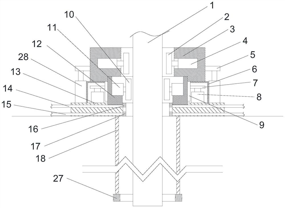
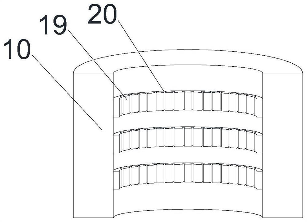
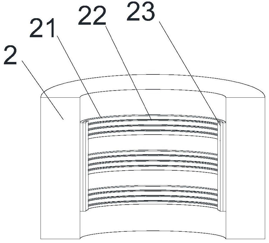
[0027] Such as Figure 1~5 As shown, this embodiment includes a sleeve 18 and a base 13 arranged at the upper end of the sleeve 18, the middle of the base 13 is provided with a bottom hole for the waste foundation pile 1 to pass through, and an upper ring seat is fixed on the base 13 3. A lower ring seat 12 coaxial with the upper ring seat 3 is provided on the lower inner wall of the upper ring seat 3, and an annular toothed belt 9 is installed on the outer peripheral wall of the lower ring seat 12. There are two through holes, and a waterproof housing 6 is provided in each of the through holes, the motor 8 is placed in the waterproof housing 6, and the output end of the motor 8 is equipped with a gear 7, and in the waterproof housing 6 The housing 6 is provided with an opening on the side wall facing the lower ring seat 12, and a part of the gear 7 passes through the opening and cooperates with the annular toothed belt 9, along the circumferential direction of the upper ring ...

Embodiment 2

[0033] Such as Figure 1~5 As shown, in this embodiment, on the basis of Embodiment 1, a plurality of spray heads 24 are uniformly arranged on the inner circumferential wall of the bottom hole along the circumferential direction of the bottom hole, and two groups of spray holes are respectively opened on the spray heads 24 16 and two groups of backflow holes 17, and the horizontal height of the spray hole 16 is greater than the horizontal height of the backflow hole 17, and a water storage chamber 25 and a sedimentation chamber 26, which are independent of each other, are respectively arranged inside the nozzle 24. One group of spray holes 16 communicates with the water storage chamber 25, two groups of return holes 17 communicate with the sedimentation chamber 26, the water inlet pipe 14 runs through the outer wall of the base 13 and communicates with the water storage chamber 25, and the outlet pipe 15 runs through the base 13 The outer side wall of the tube communicates wit...

Embodiment 3

[0037] Such as Figure 1~5 As shown, on the basis of Embodiment 1, the present embodiment is also provided with a drill tube 27 at the lower end of the casing 18, the outer diameter of the drill tube 27 is greater than the outer diameter of the casing 18, and the drill tube 27 The inner diameter is smaller than the inner diameter of the sleeve 18 . When the outer diameter of the drill pipe 27 is greater than the outer diameter of the casing 18, and the inner diameter of the drill pipe 27 is smaller than the inner diameter of the casing 18, so that the drill pipe 27 can expand the casing pipe 18 when drilling and moving down after cutting into the soil layer. The gap ensures that the air enters the gap while ensuring the smooth progress of the water injection process.

[0038] The main function of the sleeve 18 is to separate the foundation pile 1 from the surrounding soil layer. During the operation, the selection of the sleeve 18 is different according to the different topog...


PUM


Abstract

The invention provides a nondestructive pile drawing machine. The nondestructive pile drawing machine comprises a sleeve and a base, wherein an upper ring seat is fixed on the base, a lower ring seatis arranged on the inner wall of the lower part of the upper ring seat, an annular toothed belt is arranged on the outer circumferential wall of the lower ring seat, two through holes are formed in the lower part of the upper ring seat, a plurality of bearing plates are arranged on the outer circumferential wall of the upper part of the upper ring seat in the circumferential direction of the upperring seat, a plurality of ejection cylinders are arranged on the base, and the output ends of the ejection cylinders are connected with the bearing plates; and a plurality of secondary cylinders arearranged on the inner circumferential wall of the upper portion of the upper ring seat in the radial direction of the upper ring seat, a secondary clamping head is installed on each secondary cylinder, a plurality of primary cylinders are arranged on the inner circumferential wall of the lower ring seat in the radial direction of the lower ring seat, and a primary clamping head is installed on each primary cylinder. According to the nondestructive removal device, the sleeve is put on the periphery of the foundation pile, so that the foundation pile is isolated from an external soil layer, andthen the upper ring seat and the lower ring seat are used for respectively carrying out vertical lifting and annular rotation on the foundation pile; and the purpose of pile pulling is achieved through alternate execution of lifting and rotating actions.

Description

technical field [0001] The invention relates to the field of underground engineering construction, in particular to a device for non-destructively removing abandoned engineering pile foundations, enclosure anchor piles or other columnar reinforced concrete structures remaining in complex strata. Background technique [0002] With the rapid development of the national economy and the continuous acceleration of the urbanization process, the resident population of cities in my country is increasing year by year. The contradiction between the rising population and the increasingly scarce land resources is intensifying. Major cities have set off a wave of underground space development. The development and utilization of underground space can not only greatly relieve urban traffic pressure such as underground railways and underground parking lots, but also expand the activity space of citizens such as underground commercial streets and underground museums. In terms of energy savin...

Claims


Application Information

Patent Timeline
Patent Type & Authority Patents(China)
IPC IPC(8): E02D9/02E02D13/00
CPCE02D9/02E02D13/00E02D2300/0001
Inventor 郭亮王敏晰张军伟钱德良廖明伟裴春王保权纪佑军陈秋雨顾蒙娜
Owner SOUTHWEST PETROLEUM UNIV
Why Eureka
Try Eureka