Pneumatic impact reamer and reaming construction process

The technology of hole reamer and air guide hole is applied in the field of reamer, which can solve the problems of increasing the cost of mud use, affecting the drilling efficiency of hole reaming, complicated binding structure, etc., so as to improve the effect of hole cleaning and the efficiency of hole reaming and rock breaking. The effect of improving and high rock breaking efficiency

Pending Publication Date: 2019-11-05
九江廊威工程机械有限公司
View PDF0 Cites 4 Cited by
  • Summary
  • Abstract
  • Description
  • Claims
  • Application Information

AI Technical Summary

Problems solved by technology

[0003] (1) The bundled impact reamer uses several conventional down-the-hole hammers and drill bits to bind on the mandrel to realize the function of large-diameter hole reaming. It has the following disadvantages: 1). The binding structure is complicated and the reliability is low; 2. ). The drill bit inevitably produces eccentric wear
Because of these defects, the bundled impact reamer has not been widely used in the market
[0004] (2) Existing cone reamers, hob reamers, etc. have low drilling efficiency in hard rock reaming drilling, and a large amount of high-ratio mud is used, resulting in high construction costs
[0005] (3) The existing reaming construction technology adopts mud chip removal. In order to effectively discharge the cuttings in the drill hole, a large amount of high-ratio mud must be used, which will increase the cost of mud use
Moreover, even with a high-ratio mud, there are still large particles of cuttings remaining in the hole, which requires secondary crushing of the drill bit, which affects the drilling efficiency of the hole reaming

Method used


Image

  • Pneumatic impact reamer and reaming construction process
  • Pneumatic impact reamer and reaming construction process
  • Pneumatic impact reamer and reaming construction process

Examples


Embodiment 1

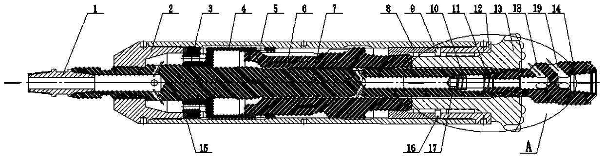
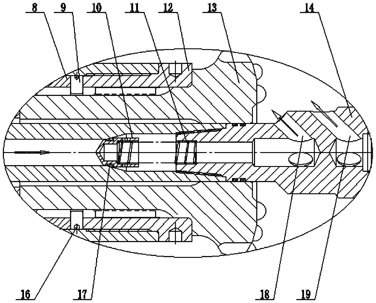
[0028] like Figure 1-2 As shown, a pneumatic impact reamer, the reamer is connected to the drilling machine through the drill pipe, including the upper joint 1, the upper end cover 2, the mandrel 7, the outer cylinder 5, the hammer 6 and the drill bit 13, and the upper joint 1 adopts a conversion buckle Type upper joint 1, the upper joint 1 is connected with the air supply end, the upper joint 1 is connected with the mandrel 7, the mandrel 7 is located on the central axis of the outer cylinder 5, the upper end cover 2 is connected with the mandrel 7 and the outer cylinder 5 through threads, and the outer cylinder 5 is successively fitted with a support sleeve 3 and a bushing 4, the hammer 6 is set inside the bushing 4, the outer cylinder 5 and the spacer 8, the bushing 4 and the spacer 8 are respectively located at both ends of the hammer 6, and the drill bit 13 passes through The spline sleeve 12 is fixedly installed inside the outer cylinder 5, and the drill bit 13 is locat...

Embodiment 2

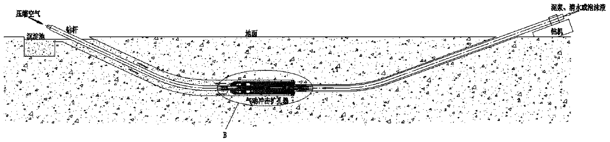
[0036] like Figure 3-4 As shown, a chip removal and reaming process in a drill pipe with a pneumatic impact reamer mainly uses a pneumatic percussion reamer described in Example 1 to realize the chip removal and reaming process in a drill pipe. The specific implementation process is as follows:

[0037] A plurality of air guide holes 18 and liquid guide holes 19 are set on the mandrel 7 of the reamer or the righting joint 14, as the passage for gas and liquid to enter the drill hole; the pneumatic impact reamer (abbreviated as reamer) is used for the pilot hole Reaming construction after the construction is completed. After the construction of the pilot hole is completed, the pilot drill bit is removed, and the liquid delivery end of the reamer is connected to the drill pipe connected to the pilot bit before. The air supply end is also connected to the drill pipe, and the air supply end is drilled The rod is then connected with the air compressor through a rotary joint and a ...


PUM


Abstract

The invention discloses a pneumatic impact reamer and a reaming construction process. The pneumatic impact reamer comprises an upper joint, an upper end cover, a central spindle, an outer cylinder, apunch hammer and a drill. The upper joint belongs to a switching buckle type upper joint. The upper joint is connected with the central spindle. The upper end cover is in threaded connection with thecentral spindle and the outer cylinder. A supporting sleeve and a bushing are sleeved with the outer cylinder in sequence. The punch hammer is sleeved with the bushing, the outer cylinder and a spacersleeve. The drill is fixedly mounted in the outer cylinder through a spline sleeve. A centralizing joint is arranged at the end, far away from the upper joint, of the drill. The centralizing joint isprovided with a plurality of air guide holes and liquid guide holes. According to the pneumatic impact reamer and the reaming construction process provided by the invention, compared with a bundled impact reamer, the pneumatic impact reamer is simpler in structure, free of welded components, integrally more resistant to impact and more reliable in operation; the pneumatic impact reamer is much larger than the bundled impact reamer through the effective impacting mass of the punch hammer, can reach higher impacting energy and has much higher rock breaking efficiency.

Description

technical field [0001] The invention relates to the technical field of hole reamers, in particular to a pneumatic impact reamer and a hole reaming construction process. Background technique [0002] In the process of horizontal directional crossing pipe laying construction, the reamer is used for reaming construction after the pilot hole construction is completed. Existing reamers used in rock formations include: bundled impact reamers, roller reamers, and hob reamers. There are certain defects in using these reamers for horizontal directional crossing pipelaying construction. [0003] (1) The bundled impact reamer uses several conventional down-the-hole hammers and drill bits to bind on the mandrel to realize the function of large-diameter hole reaming. It has the following disadvantages: 1). The binding structure is complicated and the reliability is low; 2. ). The drill bit inevitably produces eccentric wear. Because of the existence of these defects, the bundled impact...

Claims


Application Information

Patent Timeline
Patent Type & Authority Applications(China)
IPC IPC(8): E21B7/28E21B4/06E21B10/00E21B17/10E21B17/07E21B17/04E21B21/00
CPCE21B4/06E21B7/28E21B10/00E21B17/04E21B17/07E21B17/1078E21B21/00
Inventor 周升风
Owner 九江廊威工程机械有限公司
Why Eureka
Try Eureka