Field detection device, system and method for achieving no maintenance of gas density relay

A gas density, on-site detection technology, applied in the field of electric power, can solve the problems of reduced insulation strength, flashover, damage and other problems on the surface of insulating parts

Pending Publication Date: 2019-11-05
SHANGHAI ROYE ELECTRICAL CO LTD
View PDF0 Cites 2 Cited by
  • Summary
  • Abstract
  • Description
  • Claims
  • Application Information

AI Technical Summary

Problems solved by technology

3) When the temperature drops, too much moisture may form condensation water, which will significantly reduce the insulation strength of the surface of the insulating part, or e

Method used


Image

  • Field detection device, system and method for achieving no maintenance of gas density relay
  • Field detection device, system and method for achieving no maintenance of gas density relay
  • Field detection device, system and method for achieving no maintenance of gas density relay

Examples


Embodiment 1

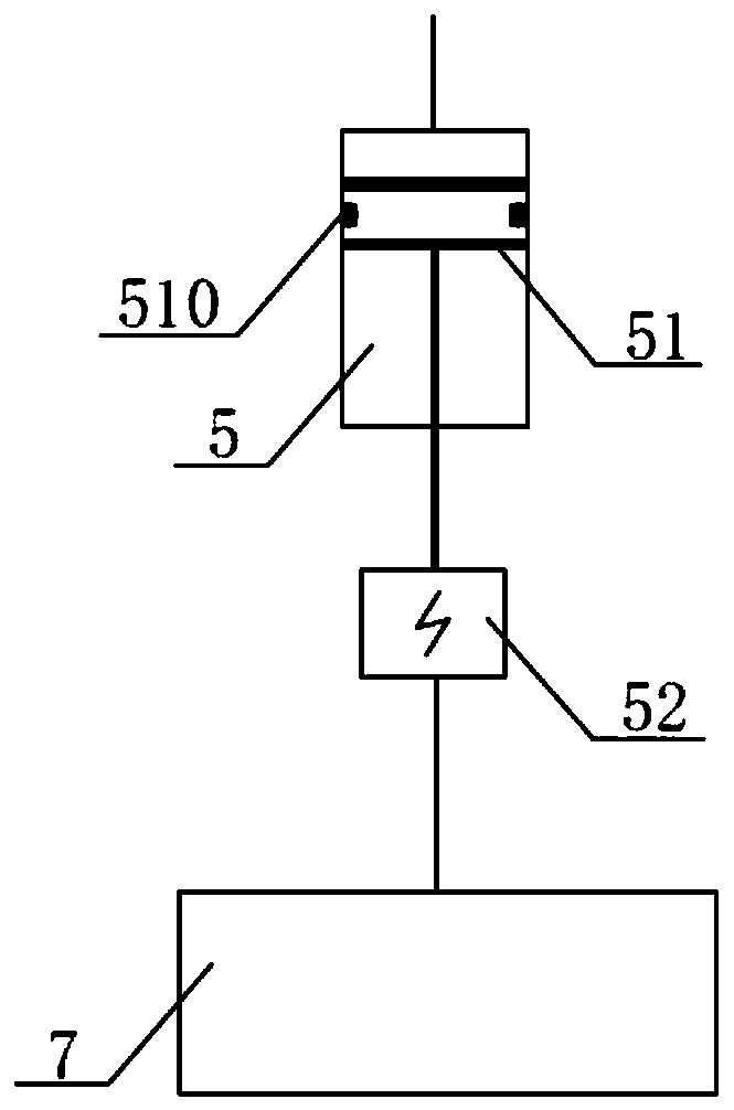
[0155] Such as figure 1 As shown, the on-site detection device includes a pressure regulating mechanism 5 and an intelligent control unit 7 . The pressure regulating mechanism 5 is provided with an interface connected with the gas circuit of the gas density relay, and the pressure regulating mechanism 5 is configured to adjust the pressure rise and fall of the gas circuit of the gas density relay, so that the gas density relay generates Contact action; the intelligent control unit 7 is connected with the pressure regulating mechanism 5 and is configured to realize the control of the pressure regulating mechanism 5; wherein, the contact signal includes alarm and / or lockout.

[0156] The pressure regulating mechanism 5 of the present embodiment is a cavity with an open end, and a piston 51 (the piston 51 is provided with a sealing ring 510) is arranged in the cavity, and an adjustment rod is connected to one end of the piston 51, and the adjustment rod The outer end is connecte...

Embodiment 2

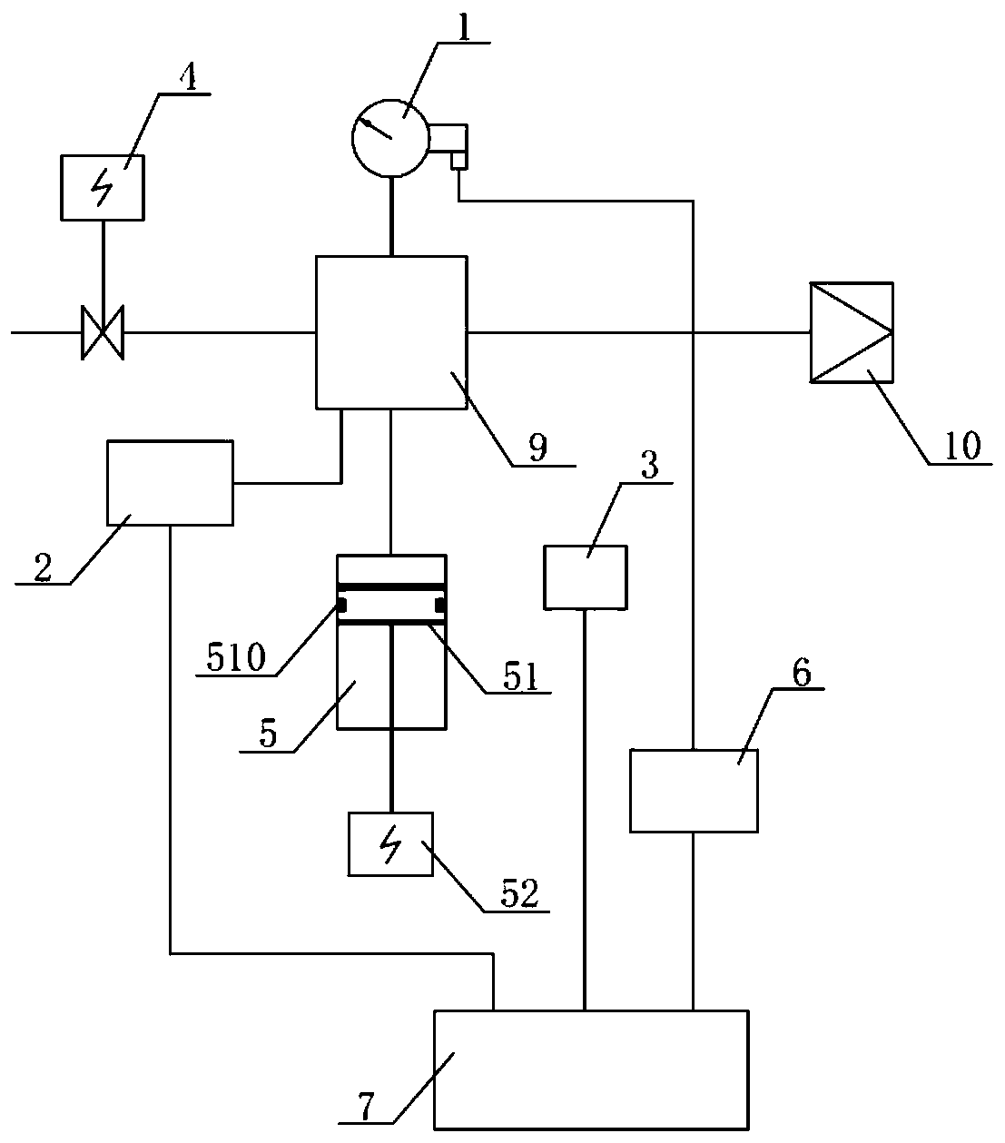
[0159] Such as figure 2 As shown, the on-site detection device of this embodiment has a pressure sensor 2 , a temperature sensor 3 , a valve 4 , an online verification contact signal sampling unit 6 , a multi-way joint 9 and an air supply interface 10 compared with the first embodiment. The valve 4 , the pressure sensor 2 , the pressure regulating mechanism 5 and the air supply interface 10 are arranged on the multi-way joint 9 .

[0160] Specifically, in the verification state, the air inlet of the valve 4 is provided with an interface that communicates with the electrical equipment, and its air inlet is sealed and connected to the electrical equipment and communicated with the air chamber of the electrical equipment. The gas outlet of 4 communicates with the detected gas density relay 1 through the multi-way joint 9; the pressure sensor 2 communicates with the gas density relay 1 on the gas path through the multi-way joint 9; the pressure regulating mechanism 5 communicates...

Embodiment 3

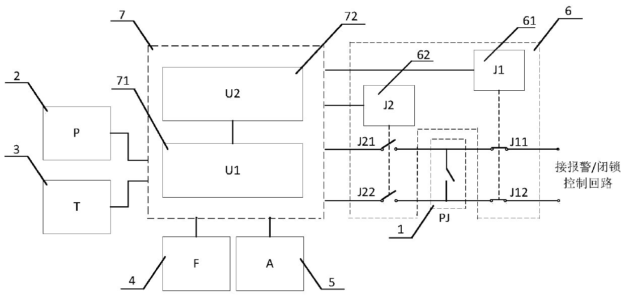
[0168] The online verification contact signal sampling unit 6 mainly completes the sampling of the contact signal of the gas density relay 1 . That is, the basic requirements or functions of the on-line verification contact signal sampling unit 6 are: 1) It does not affect the safe operation of electrical equipment during verification, that is, when the contact of the gas density relay 1 moves during verification, it will not affect the electrical equipment. Safe operation of the equipment; 2) The contact signal control circuit of the gas density relay 1 does not affect the performance of the on-site detection device, especially the performance of the intelligent control unit 7, and does not cause damage to the on-site detection device or affect the test work.

[0169] Such as image 3 As shown, the online verification contact signal sampling unit 6 of this embodiment is mainly composed of a relay J1 (61) and a relay J2 (62). For the gas density relay whose contacts are norma...


PUM


Abstract

The invention provides a field detection device for achieving no maintenance of a gas density relay. The field detection device comprises a pressure regulation mechanism and an intelligent control unit, wherein the increase and decrease of the pressure of the pressure regulation mechanism are controlled by the intelligent control unit to complete the field detection of the gas density relay, and no maintainer is needed to operate on site to achieve no maintenance of the gas density relay and greatly improve the efficiency and reliable and safe running of power grids. The invention further provides a field detection system containing the field detection device. The invention further provides a field detection method for supporting normal running of the field detection device.

Description

technical field [0001] The invention relates to the field of electric power technology, in particular to an on-site detection device, system and method for realizing maintenance-free gas density relays applied to medium and high-voltage electrical equipment. Background technique [0002] Gas density relay is generally used to monitor and control the density of insulating gas in high-voltage and medium-voltage electrical equipment. It is equipped with a contact signal control circuit inside. When a gas leak occurs, the contact of the gas density relay will act to generate a contact signal, and the contact signal control circuit will send an alarm or block according to the contact signal, so as to realize the safe operation protection of electrical equipment. [0003] At present, SF6 (sulfur hexafluoride) electrical equipment has been widely used in the power sector and industrial and mining enterprises, which has promoted the rapid development of the power industry. In recen...

Claims


Application Information

Patent Timeline
IPC IPC(8): G01N9/00G01D21/02G05B19/042G01R31/327
CPCG01D21/02G01N9/00G01R31/3271G01R31/3272G01R31/3274G05B19/0423
Inventor 曾伟常敏黄小泵廖海明金海生王恩林
Owner SHANGHAI ROYE ELECTRICAL CO LTD
Why Eureka
Try Eureka