Collimator and laser

A collimator and fiber optic component technology, applied in the field of collimators and lasers, can solve problems such as laser spectrum drift, damage to the laser system, unstable output power, etc., and achieve the effect of reducing costs and saving layout space

Pending Publication Date: 2019-11-05
ZHUHAI GUANGKU TECH CO LTD
View PDF0 Cites 0 Cited by
  • Summary
  • Abstract
  • Description
  • Claims
  • Application Information

AI Technical Summary

Problems solved by technology

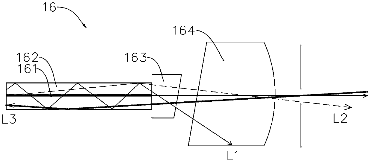
refer to figure 2 and image 3 , figure 2 is a structural diagram of the collimator 16, the collimator 16 mainly includes a core 161, a cladding 162, an end cap 163 and a C lens 164, image 3 It is a schematic diagram of the optical path of the forward and reverse light transmission through the collimator. The normal main signal laser is output along the optical axis in a straight line, while the L1 light is the residual pump light of the front-end amplification stage. The divergence angle is larger than the optical aperture of the device during forward transmission. It will be absorbed by the C lens 164 or the inner wall of the device, and the heat will affect the performance parameters such as insertion loss, isolation, and beam quality of the high-power fiber-to-free space isolator. L2 light is the signal light leaked to the cladding, and is absorbed by the inner wall of the device. Absorb heat or transmit into free space, reduce the output M^2 index, and affect the use effect of the laser. L3 light is the beam that is reversely coupled into the fiber cladding in the free space during the use of the laser, and transmitted into the amplification stage, which can cause the laser spectrum to drift 1. The output power is unstable or even damages the laser system, so it is necessary to install a power stripper 15 in the laser to filter the above-mentioned light of L1, L2, and L3, so as to ensure the stable use of the laser, but this will also cause the increase of the laser system. The degree of complexity increases the structural layout space and increases the corresponding cost

Method used


Image

  • Collimator and laser
  • Collimator and laser
  • Collimator and laser

Examples


Embodiment Construction

[0027] refer to Figure 4 to Figure 5 , the collimator 3 includes an optical fiber assembly, an end cap 33, an output lens 34 and a sleeve 38, the optical fiber assembly includes a core 31 and a cladding assembly 32, the core 31 is located in the cladding assembly 32, and the outer surface of the cladding assembly 32 A functional ring groove 321 is provided, and the functional ring groove 321 extends along the circumferential direction of the fiber core 31. The functional ring groove 321 is sunken from the outer surface of the cladding component 32 toward the fiber core 31. The functional ring groove 321 is provided with a bottom wall 322 and is located at The side walls 323 at both ends of the axial direction, the bottom wall 322 of the functional ring groove 321 is parallel to the axial direction of the fiber core 31, and the two side walls 321 are respectively located at the two axial ends of the bottom wall 322 of the fiber core 31, and the two side walls 321 are respectiv...


PUM


Abstract

The invention provides a collimator and a laser. The collimator comprises an optical fiber assembly, an end cap and an output lens, wherein the optical fiber assembly comprises a fiber core and a cladding assembly, the fiber core is located in the cladding assembly, the outer surface of the cladding assembly is provided with a functional ring groove, the functional ring groove extends in the circumferential direction of the fiber core, the end of the fiber core is in butt joint with a first end of the end cap, and the output lens and a second end of the end cap are arranged oppositely. By forming the functional ring groove in the cladding assembly in the circumferential direction, light of L1, L2, L3 and L4 in the prior art is filtered to the outside by the functional ring groove, a main signal laser is still transmitted and output along the fiber core to ensure insertion loss, isolation, beam quality and other performance parameters, and the laser does not use a separately set power stripper any more, thereby saving arrangement space and reducing cost.

Description

technical field [0001] The invention relates to the field of optical devices, in particular to a collimator and a laser. Background technique [0002] The collimator belongs to an optical component used for input and output of optical fiber communication optical devices, and the collimator is widely used in lasers. Refer to figure 1 , figure 1 It is a schematic diagram of the optical path of an existing commonly used laser. The laser includes a seed light source 11, a first-stage amplifier 12, an in-line isolator 13, a second-stage amplifier 14, a power stripper 15, and a collimator 16 arranged along the optical path in sequence. The light source 11 outputs laser light, and the laser light passes through the first-stage amplifier 12 , the in-line isolator 13 and the second-stage amplifier 14 to realize two-stage amplification, and then passes through the power stripper 15 and then collimates the output through the collimator 16 . refer to figure 2 and image 3 , figur...

Claims


Application Information

Patent Timeline
Patent Type & Authority Applications(China)
IPC IPC(8): G02B6/32G02B6/24H01S3/13
CPCG02B6/24G02B6/32H01S3/1302
Inventor 邓剑钦黄汉凯
Owner ZHUHAI GUANGKU TECH CO LTD
Why Eureka
Try Eureka