Turning-milling composite machine tool based on auxiliary machine vision laser heating and monitoring method

A technology of laser heating and machine vision, which is applied in metal processing, metal processing equipment, metal processing machinery parts, etc., can solve the problems of inability to realize self-adaptive adjustment of cutting parameters and laser parameters, achieve compact structure, save space, and increase the degree of freedom Effect

Inactive Publication Date: 2019-11-08
HARBIN UNIV OF SCI & TECH
View PDF13 Cites 8 Cited by
  • Summary
  • Abstract
  • Description
  • Claims
  • Application Information

AI Technical Summary

Problems solved by technology

[0004] The purpose of the present invention is to provide a machine vision-based laser heating-assisted turning-milling compound machine tool to solve the problem that the cutting parameters and laser parameters cannot be adjusted adaptively in the laser heating-assisted processing process in the prior art.

Method used


Image

  • Turning-milling composite machine tool based on auxiliary machine vision laser heating and monitoring method
  • Turning-milling composite machine tool based on auxiliary machine vision laser heating and monitoring method
  • Turning-milling composite machine tool based on auxiliary machine vision laser heating and monitoring method

Examples


specific Embodiment approach 1

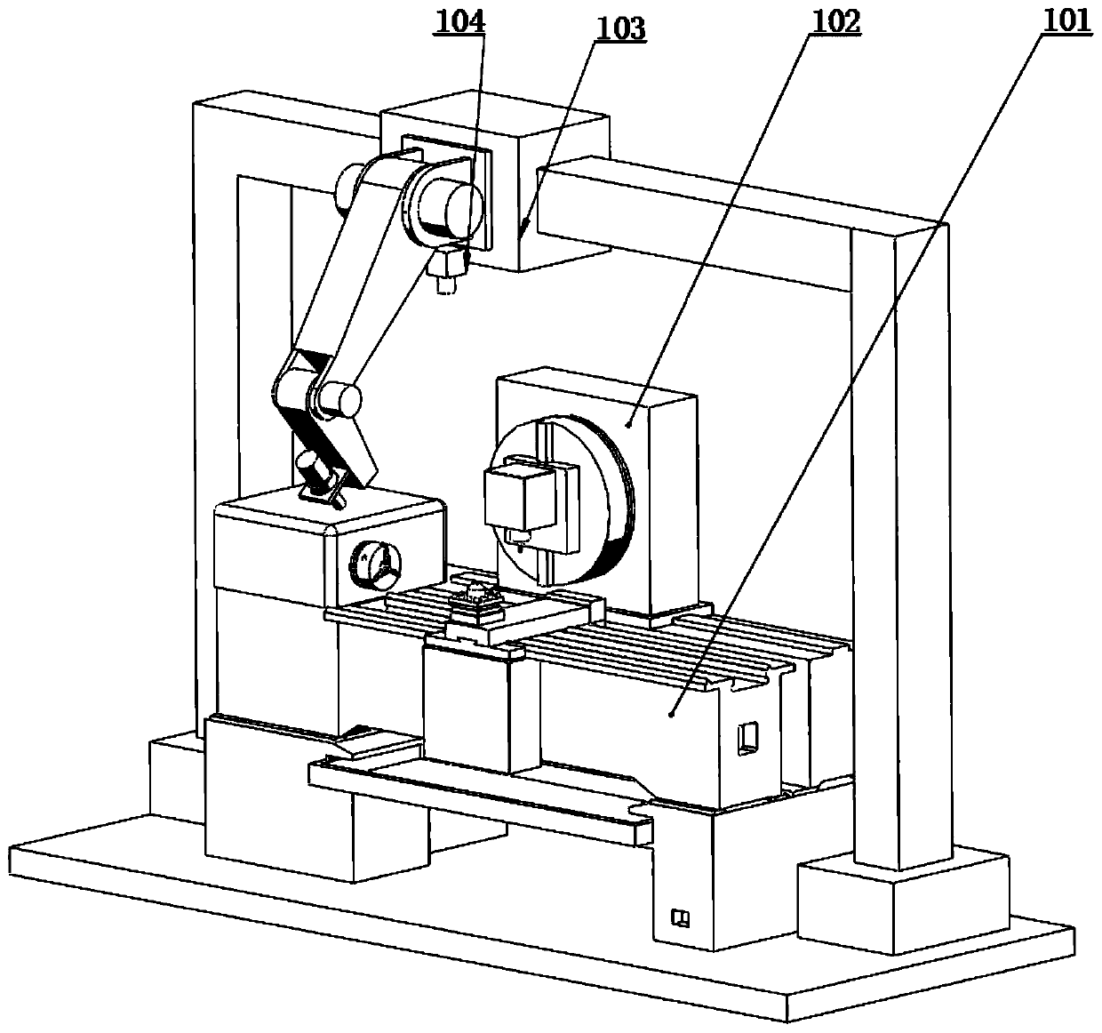
[0036] Specific implementation mode one: refer to Figure 1 to Figure 4 Describe this embodiment in detail. The machine vision-based laser heating-assisted turning-milling compound machine tool described in this embodiment includes: a lathe module 101, a milling machine module 102, a manipulator module 103, and a machine vision module 104;

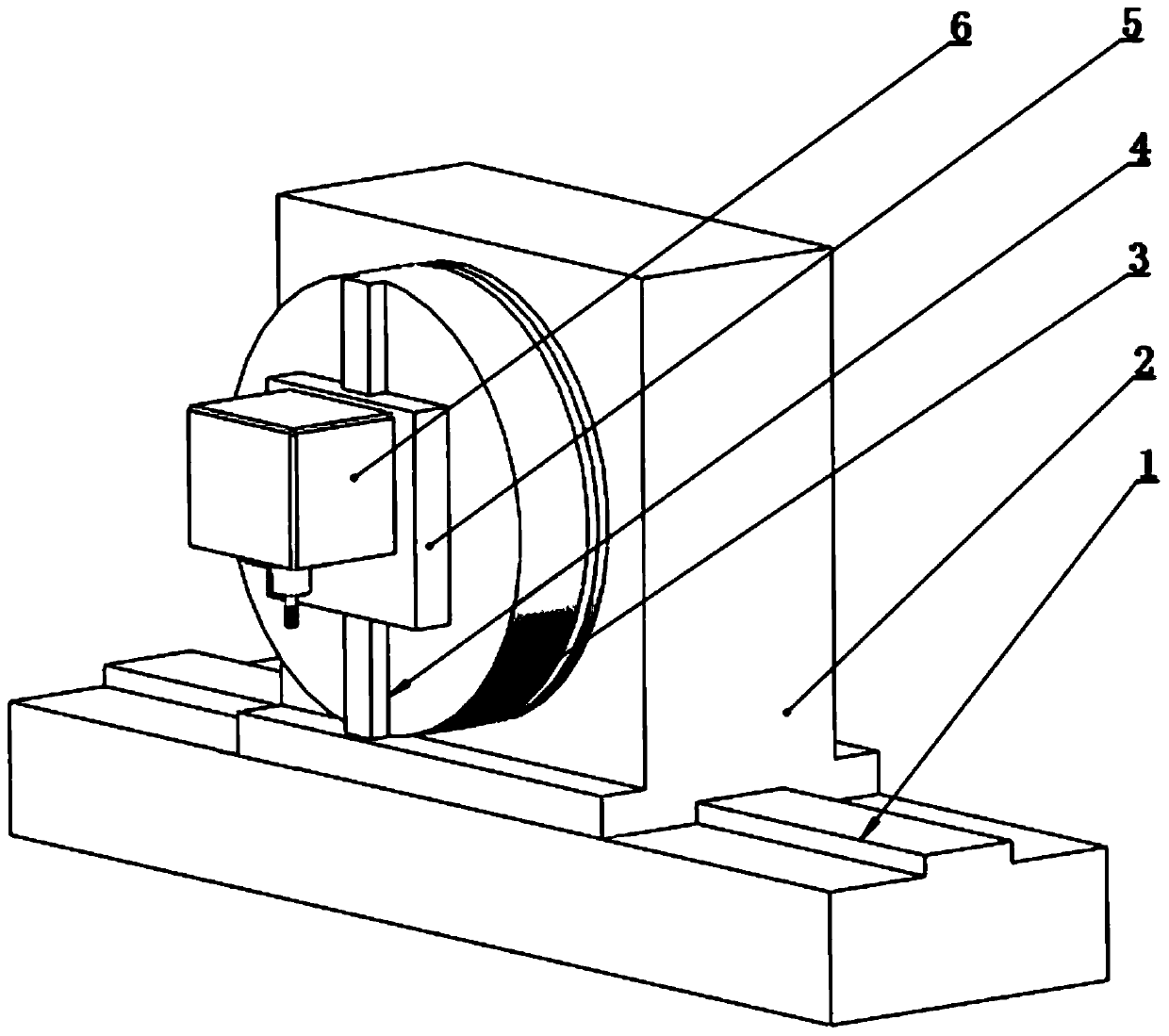
[0037] The milling machine module 102 includes a longitudinal guide rail 1, a milling machine base 2, a circular base 3, a circular base guide rail 4, a spindle box slider 5 and a milling machine spindle box 6; the milling machine base 2 is arranged on the longitudinal guide rail 1, and the milling machine base 2 and The longitudinal guide rail 1 is slidingly connected; the circular base 3 is arranged on the side of the milling machine base 2 in the sliding direction, and the circular base 3 is provided with a telescopic part, and the telescopic part is embedded in the milling machine base 2, and is connected with the milling machine base 2...

specific Embodiment approach 2

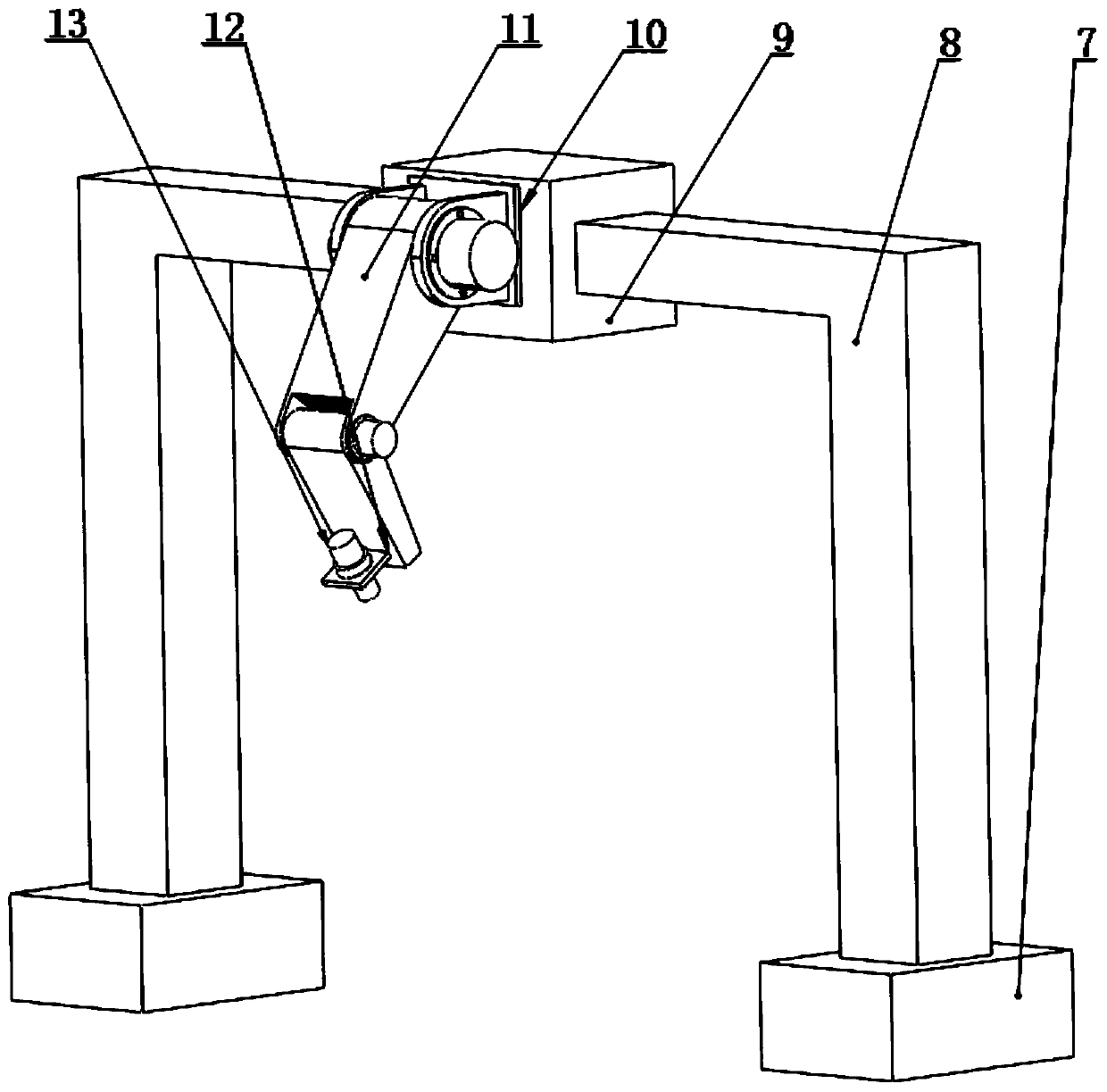
[0044] Embodiment 2: This embodiment is a further description of Embodiment 1. The difference between this embodiment and Embodiment 1 is that the sliding range of the beam slider 9 is smaller than the length of the beam 8 and larger than the workpiece the maximum length of .

specific Embodiment approach 3

[0045] Embodiment 3: This embodiment is a further description of Embodiment 1. The difference between this embodiment and Embodiment 1 is that the manipulator module 103 has a gantry structure.


PUM


Abstract

The invention discloses a turning-milling composite machine tool based on auxiliary machine vision laser heating and a monitoring method, relating to the technical field of laser heating auxiliary machining, and aiming at solving the problem that cutting parameters and laser parameters cannot be adaptively adjusted in the laser heating auxiliary machining process in the prior art. The turning-milling composite machine tool comprises a turning machine module, a milling machine module, a mechanical hand module and a machine vision module. A mechanical hand is installed on a gantry type guide rail, so that the space in the machining process is greatly saved, and the structure is more compact; a laser is installed on a mechanical arm, so that the degree of freedom of the laser is increased during the heating auxiliary machining process; a rigid connection mode is adopted between the turning machine and the milling machine so that the respective functions are integrated, and the machining efficiency is greatly improved; data collected by a camera is transmitted to the machine tool and laser in real time, so that the cutting parameters and laser parameters during machining can be adapted.

Description

technical field [0001] The invention relates to the technical field of laser heating-assisted processing, in particular to a machine vision-based laser heating-assisted turning-milling compound machine tool. Background technique [0002] Laser heating assisted milling technology is to irradiate a high-energy laser beam on the material removal area, increase the local temperature of the workpiece material in a short time, change the cutting performance of the material, and then use the tool for processing. By heating the material, the plasticity of the material is improved, the yield strength is reduced to below the fracture strength, the cutting force is reduced, the tool wear is reduced, and the cutting chatter is reduced, thereby achieving the purpose of improving processing efficiency, reducing cost, and improving the quality of the processed surface. [0003] During laser heating-assisted processing, when the laser beam irradiates the material removal area, due to variou...

Claims


Application Information

Patent Timeline
IPC IPC(8): B23P23/02B23P25/00B23Q17/24B23Q11/00
CPCB23P23/02B23P25/006B23Q11/00B23Q17/2409
Inventor 吴雪峰周贤良王明宇
Owner HARBIN UNIV OF SCI & TECH
Why Eureka
Try Eureka