Reinforcing steel bar derusting device for building construction
A technology for building construction and steel bars, which is applied in the field of steel bar rust removal devices for building construction, can solve problems such as poor rust removal effect and affect user work efficiency, and achieve the effects of convenient movement, improved rust removal effect, and improved work efficiency
- Summary
- Abstract
- Description
- Claims
- Application Information
AI Technical Summary
Problems solved by technology
Method used
Image

Examples
Embodiment 1
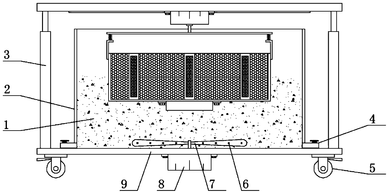
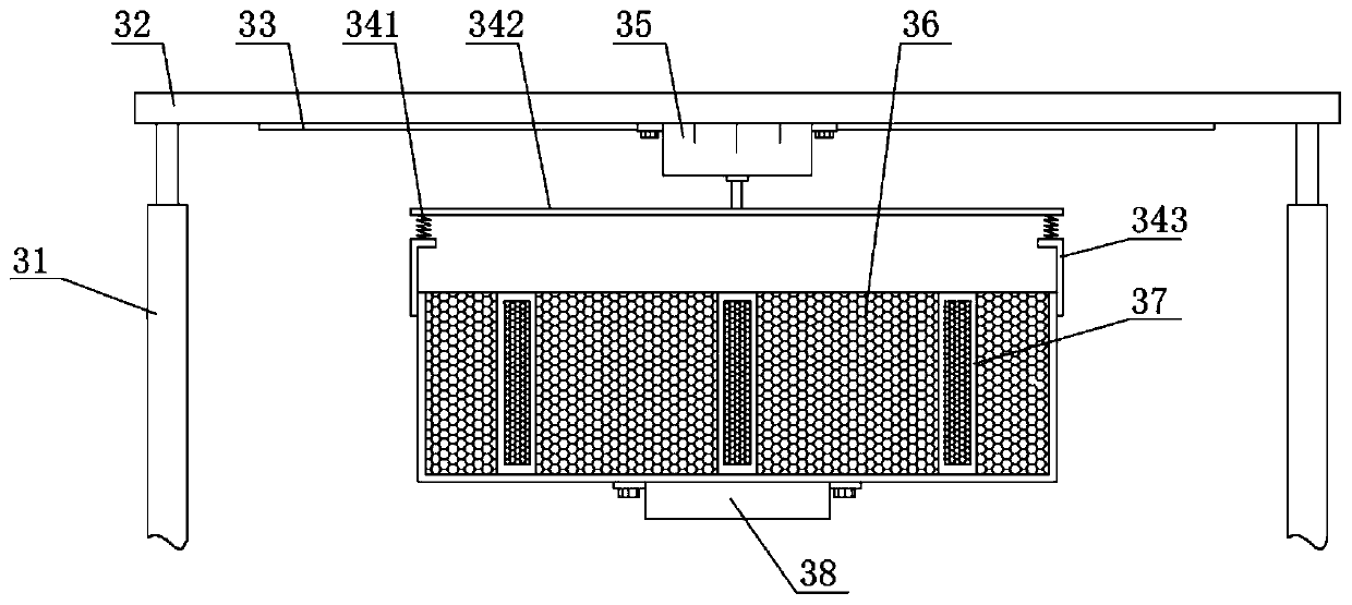
[0020] see Figure 1-Figure 3 , the present invention provides a technical solution: a steel bar rust removal device for building construction, including a support base plate 9, a liquid storage tank 2 is welded in the middle of the upper surface of the support base plate 9, and a sewage discharge pipe 4 is welded at the bottom of the liquid storage tank 2 , the inside of the liquid storage tank 2 is provided with a pickling liquid 1, the use of the pickling liquid 1 is a prior art, the top of the liquid storage tank 2 is provided with a rust removal mechanism 3, the rust removal mechanism 3 includes a support top plate 32, and the support top plate 32 A height adjustment member 31 is welded at the joint with the support base plate 9, a second drive motor 35 is arranged on the middle part of the lower surface of the support top plate 32, and the output end of the second drive motor 35 is welded with a first connector 342. The first connector 342 The rust removal box 36 is arra...
Embodiment 2
[0025] On the basis of Embodiment 1, in order to make the function of the derusting device more abundant, in this embodiment, preferably, the first drive motor 8 is welded in the middle of the lower surface of the support base plate 9, and the output end of the first drive motor 8 is set There is a stirring member 7, and the first drive motor 8 is electrically connected to the power supply through a switch;
[0026] In order to make the connection between the stirring member 7 and the first driving motor 8 more reliable, in this embodiment, preferably, the stirring member 7 and the first driving motor 8 are fixedly connected by welding, and the surface of the stirring member 7 is provided with a limited through hole 6 , the limit through hole 6 prevents the stirring member 7 from being damaged due to excessive resistance, and the power supply of the first driving motor 8 is connected during use, so that the first driving motor 8 drives the stirring member 7 to rotate, thereby p...
PUM
 Abstract
Description
Claims
Application Information
PatSnap Eureka turns technology decisions into work you can execute. Powered by our Innovation Knowledge Graph, it runs expert workflows across engineering, life sciences, materials and intellectual property. Get your review-ready output in minutes.


