Machine vision-based defect detection method of chemical fiber spinning nozzle hole

A technology of machine vision and detection method, applied in the direction of optical testing flaws/defects, instruments, measuring devices, etc., can solve the problems of low detection efficiency, high detection cost, small diameter of spinneret, etc., to reduce labor intensity and ensure accurate The effect of improving the detection efficiency

Inactive Publication Date: 2019-11-12
ZHENGZHOU UNIV
View PDF10 Cites 6 Cited by
  • Summary
  • Abstract
  • Description
  • Claims
  • Application Information

AI Technical Summary

Problems solved by technology

[0002] Defect detection is an essential link in the production of products. The holes of the chemical fiber spinneret are prone to defects such as clogging, burrs, and out-of-roundness in the process of manufacturing and spinning, and the spinneret hole diameter is small and the number of holes is large. The traditional Manual inspection is done with the help of a microscope, which has problems such as low detection efficiency, high labor intensity, unobjective detection results, and high detection cost, which obviously cannot meet the needs of modern enterprise development.

Method used


Image

  • Machine vision-based defect detection method of chemical fiber spinning nozzle hole
  • Machine vision-based defect detection method of chemical fiber spinning nozzle hole
  • Machine vision-based defect detection method of chemical fiber spinning nozzle hole

Examples


Embodiment 1

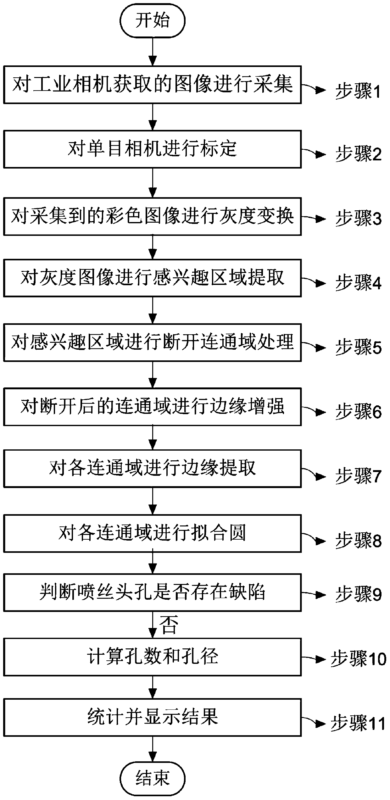
[0033] This embodiment provides a method for detecting defects in the hole of a chemical fiber spinneret based on machine vision, such as figure 1 As shown, it is characterized in that it includes the following process steps:

[0034] Step 1. Collect the images acquired by the industrial camera;

[0035] Step 2. Calibrate the camera to obtain the relationship between pixel size and actual size;

[0036] Step 3. Carry out grayscale transformation to the collected color image;

[0037] Step 4. Carry out region of interest (Regions of Interest, ROI) extraction to the image after carrying out gray-scale transformation;

[0038] Step 5. Disconnect connected domain processing to the extracted ROI region;

[0039] Step 6. Carry out edge enhancement to the disconnected connected domain;

[0040] Step 7. Carry out edge extraction to each connected domain;

[0041] Step 8. Carry out fitting circle to each connected domain;

[0042] Step 9. Determine whether there is a defect, if n...

Embodiment 2

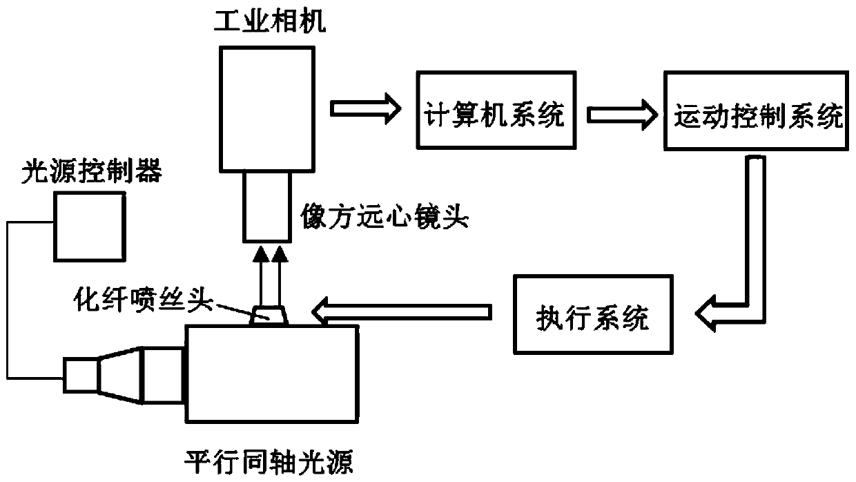
[0069] This embodiment provides a machine vision-based chemical fiber spinneret hole defect detection system, such as image 3As shown, it is characterized in that it includes the following process steps:

[0070] The light source lighting system is used to provide the light conditions required for image acquisition;

[0071] An image acquisition system, used for acquiring images and processing the images;

[0072] A computer system for image processing and display of test results;

[0073] Motion control and communication system to synchronize with the production line and trigger the camera to take pictures;

[0074] Execution system for pick-up and transfer of spinnerets.

[0075] Specifically, generally speaking, the longer the wavelength, the greater the diffraction of light, so the present invention uses a coaxial backlight with a shorter wavelength.

[0076] Specifically, since the detection target is a hole with a diameter of 50-70um, parallel coaxial backlight illu...


PUM


Abstract

The invention discloses a machine vision-based defect detection method of a chemical fiber spinning nozzle hole. The machine vision-based defect detection method involves a defect detection algorithm,a light source, an industrial camera, a computer system, a control and communication system and an execution system. By a series of pre-processing and defect detection algorithms on an image acquiredby the industrial camera, detection on defects such as plug and burrs of the chemical fiber spinning nozzle hole and on aperture and hole numbers is achieved, the detection efficiency and accuracy can be improved, the labor intensity of a worker is reduced, meanwhile, the production cost of an enterprise is reduced, and a detection result can be displayed in real time.

Description

technical field [0001] The invention relates to the field of machine vision defect detection, in particular to a machine vision-based method for detecting a hole defect in a chemical fiber spinneret. Background technique [0002] Defect detection is an essential link in the production of products. The holes of the chemical fiber spinneret are prone to defects such as clogging, burrs, and out-of-roundness in the process of manufacturing and spinning, and the spinneret hole diameter is small and the number of holes is large. The traditional Manual inspection is done with the help of a microscope, which has problems such as low detection efficiency, high labor intensity, unobjective detection results, and high detection cost, which obviously cannot meet the needs of modern enterprise development. Machine vision has the advantages of fast speed and high precision, and has become the best means of defect detection. Contents of the invention [0003] The invention provides a ma...

Claims


Application Information

Patent Timeline
Patent Type & Authority Applications(China)
IPC IPC(8): G01N21/88G01B11/12G06T7/00G06T7/13G06T7/187G06T7/62G06K9/32
CPCG01N21/8851G01B11/12G06T7/13G06T7/0004G06T7/187G06T7/62G01N2021/8887G06V10/25
Inventor 沈鹏齐凯华陈江义
Owner ZHENGZHOU UNIV
Why Eureka
Try Eureka