
Novel atomizing nozzle based on bubble cutting

A technology of atomizing nozzles and air bubbles, applied in the direction of spraying devices, liquid spraying devices, etc., can solve the problems of large particles, poor atomization effect, large average diameter of liquid mist particles, etc., and achieve small diameter of atomized particles and high working pressure Wide range, uniform and stable bubbly flow

Pending Publication Date: 2019-11-15
HEBEI UNIV OF TECH
View PDF1 Cites 7 Cited by
  • Summary
  • Abstract
  • Description
  • Claims
  • Application Information

AI Technical Summary

Problems solved by technology

[0003] The Chinese patent with the patent number ZL201310544259.8 discloses a bubble atomizing nozzle. There is a through gas flow channel in the middle of the inner core. The gas enters from the middle, the liquid enters from the bottom, and the gas enters the mixing chamber through the swirl groove. Finally, it is mixed with the liquid and sprayed, but there are the following disadvantages: 1) The average diameter of the liquid mist particles is too large when the atomization is stable
2) The atomization effect of the nozzle is not good under the lower gas-liquid two-phase pressure, and there are more large particles
3) The nozzle can only achieve good atomization quality in a narrow range of gas-liquid mass flow ratio GLR (0.07-0.1)

Method used


Image

  • Novel atomizing nozzle based on bubble cutting
  • Novel atomizing nozzle based on bubble cutting
  • Novel atomizing nozzle based on bubble cutting

Examples


Embodiment 1

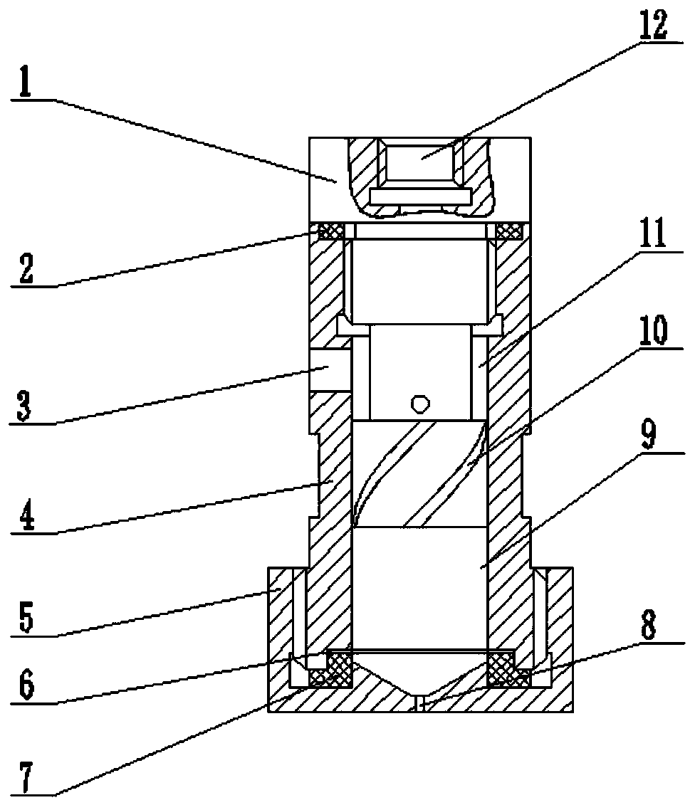
[0040] In this embodiment, the diameter of the liquid inlet hole is 2 mm, the aspect ratio of the secondary mixing chamber is 1.25:1, the bubble cutter is a 200-mesh wire mesh, and the circular hole D=1.0 mm. The nozzle hole 8 is cylindrical, with an aspect ratio of 2:1, a diameter of 1.0 mm, and a length of the nozzle hole of 2 mm.

[0041] Liquid and compressed air enter the primary mixing chamber 11 through the liquid inlet hole 3 and the first air inlet hole 12 respectively, and enter the secondary mixing chamber 9 tangentially through the swirl tank 10 after preliminary mixing; Fully mixed in the stage mixing chamber to form a gas-liquid two-phase bubble flow, which is sprayed through the nozzle hole 8 to form a uniform and stable fog torch. image 3 It is the atomization state diagram of the nozzle when the gas-liquid mass flow ratio is 0.11. It can be seen from the figure that the particles after atomization are uniform and of good quality, and a stable fog torch can be...


PUM


Abstract

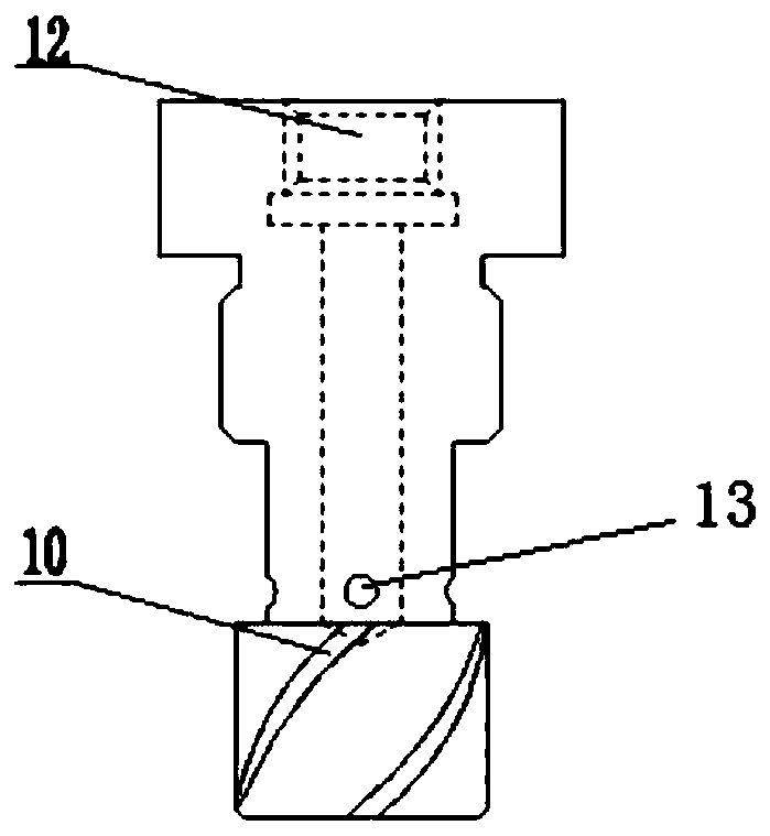
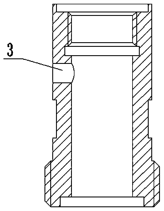
The invention provides a novel atomizing nozzle based on bubble cutting. The novel atomizing nozzle comprises an internal assembly and an external assembly, wherein closed space formed by the internalassembly and the external assembly constitutes a mixing chamber of the nozzle, the internal assembly comprises an inner core and a bubble divider, the external assembly comprises a casing and a sprayhead, a first air inlet hole is formed in the top of the inner core, an external thread is formed at the upper part of the inner core below the first air inlet hole, multiple second air inlet holes are formed in the inner core below the external thread, and swirling grooves are formed in the inner core located below the second air inlet holes; the casing is a hollow opening round tube, an internal thread at the upper part of the casing is tightly connected with the external thread on the inner core through a sealing structure, a liquid inlet hole is formed in the side surface of the casing, and an external thread is formed at the lower part of the casing; an internal thread is formed at the upper part of the spray head, a spray hole is formed in the central position of the closed end of the spray head, the bubble divider is mounted in a hollow cavity in the lower part of the casing, and the casing and the bubble divider are tightly connected with the spray head through a sealing structure. The novel atomizing nozzle has higher atomizing quality, and the average diameter of particles is smaller and more uniform.

Description

technical field [0001] The invention relates to a new type of bubble atomizing nozzle with a bubble divider inside, specifically a low-pressure and small-flow bubble atomizing nozzle with compressed air and water as the working medium. It is a low-pressure bubble atomizing nozzle with low gas consumption rate and high atomization quality, which is more efficient and energy-saving than aerospace, power, agriculture and other industries. Background technique [0002] Bubble atomization is a more efficient, economical and applicable atomization technology actively explored and developed on the basis of mechanical atomization and medium atomization. The atomization mechanism of the bubble atomization nozzle is essentially different from the atomization method of the traditional nozzle. The traditional atomization method is to realize the atomization of the liquid by means of the kinetic energy of the liquid or gas. The mechanism of bubble atomization is to inject compressed air...

Claims


Application Information

Patent Timeline
Patent Type & Authority Applications(China)
IPC IPC(8): B05B7/04
CPCB05B7/0416B05B7/0491B05B7/0483
Inventor 刘联胜裴娜王越杨华段润泽田亮李培
Owner HEBEI UNIV OF TECH
Learn More