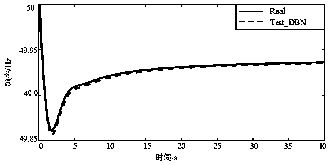
Dynamic frequency estimation measurement method after disturbance of power system

A dynamic frequency and measurement method technology, applied in the direction of measuring electricity, measuring devices, measuring electrical variables, etc., can solve the problem of difficulty in meeting the accuracy and rapidity requirements of online applications, the difficulty of truly reflecting the nonlinear dynamic characteristics of the system, and the large scale of accurate modeling. Difficulty and other issues

Inactive Publication Date: 2019-11-19
SOUTHWEST JIAOTONG UNIV
View PDF3 Cites 3 Cited by
  • Summary
  • Abstract
  • Description
  • Claims
  • Application Information

AI Technical Summary

Problems solved by technology

With the integration of new energy into the grid, the inertia of the system will decrease, and the frequency will change faster. There are higher requirements for the rapidity of online prediction of frequency stability. These methods are difficult to balance calculation accuracy and calculation efficiency.
In addition, due to the complexity, randomness, time-varying, geographical dispersion and other characteristics of the components and the system itself, it is difficult to accurately model, especially the model of the components such as the load of the system is usually difficult to accurately model, and the model parameters are usually based on Given empirical values ​​or standard values, it is difficult to truly reflect the nonlinear dynamic characteristics of the system
Therefore, the post-disturbance frequenc

Method used


Image

  • Dynamic frequency estimation measurement method after disturbance of power system
  • Dynamic frequency estimation measurement method after disturbance of power system
  • Dynamic frequency estimation measurement method after disturbance of power system

Examples


Example Embodiment

[0112] A specific implementation of the present invention is a dynamic frequency estimation and measurement method after power system disturbance, the steps of which are:

[0113] A. Training of the prediction model:

[0114] A1. Generation of initial input vector:

[0115] Record the inertia time constant H of the i-th generator in the system i ; At the same time, record the maximum mechanical power P of the generator i , Get the maximum mechanical power vector P={P 1 ,P 2 ,...,P i ,...,P I }; where i is the number of generators in the system, i∈{1,2,...,I}, I is the total number of generators in the system;

[0116] Through dynamic time domain simulation, the following 10 initial input vectors numbered (1)-(10) of the g-th generator are obtained under the n-th load level of the system: where g∈{1,2,..., I} The serial number of the removed generator in the system;

[0117] (1) Load level vector Among them, n is the number of load levels, n∈{1,2,...,N}, N is the maximum number of load...


PUM


Abstract

The invention discloses a dynamic frequency estimation and measurement method after disturbance of a power system. The method mainly comprises the following steps: A, training: A1, carrying out dynamic time domain simulation to obtain 10 initial input vectors; a2, calculating 11 secondary input vectors; a3, splicing the vectors in the steps A1 and A2 into an input eigenvalue vector; A4, carrying out dynamic time domain simulation to obtain a dynamic frequency; a5, completing the training of the prediction model according to the data in the steps A3 and A4; b, testing: B1, monitoring 10 initialtest input vectors on line; b2, if the zero element exists in the electromagnetic power vector of the generator, judging that disturbance occurs, and turning to the step B3; b3, calculating 11 secondary test input vectors; b4, connecting the vectors in the steps B1 and B3 in series to form a test input characteristic value vector; and B5, inputting the test input eigenvalue vector into a prediction model, and outputting the disturbed estimated dynamic frequency by the model. The method is rapid in estimation and measurement, high in precision and small in error.

Description

technical field [0001] The invention relates to a dynamic frequency estimation and measurement method of a power system. Background technique [0002] Frequency is an important indicator to reflect the operation status of the power system. The frequency stability of the power system means that after the power system is severely disturbed (power loss, a generator in the system fails to stop power supply), there is a large imbalance between power generation and load demand, and the system frequency can still remain stable without frequency occurrence. The ability to crash. With the development of UHV DC transmission lines, when the DC transmission lines with continuously increasing transmission capacity are disconnected due to accidents and stop power supply, the threat to the frequency stability of the receiving end system also increases. At the same time, with the large-scale development and investment of new energy, the complexity of the power grid and the security risks ...

Claims


Application Information

Patent Timeline
IPC IPC(8): G06F17/50G06Q50/06G01R31/00
CPCG06Q50/06G01R31/00
Inventor 王晓茹仉怡超
Owner SOUTHWEST JIAOTONG UNIV
Why Eureka
Try Eureka