
Flexible piezoelectric transducer and system

A flexible piezoelectric and transducer technology, applied in the field of acoustics, can solve the problems of poor energy superposition, limitations of miniaturization and integration, and short distance maintained in the propagation direction, achieve focused acoustic vortex stabilization, and improve equipment integration. The effect of superposition and enhancement of power and energy

Inactive Publication Date: 2019-11-19
吕舒晗
View PDF13 Cites 4 Cited by
  • Summary
  • Abstract
  • Description
  • Claims
  • Application Information

AI Technical Summary

Problems solved by technology

[0003] The bottleneck in the development of the application of acoustic vortex beams is that the overall circuit of the current system for generating acoustic vortex beams is complex, there are serious limitations in miniaturization and integration, and the cost is high
In addition, the current system cannot dynamically change the depth of the focal spot, resulting in narrow directivity of the transmitting array, poor energy superposition in the focal area, unstable focused acoustic vortex, and short distance maintained in the propagation direction

Method used


Image

  • Flexible piezoelectric transducer and system
  • Flexible piezoelectric transducer and system
  • Flexible piezoelectric transducer and system

Examples


Embodiment 1

[0040] In order to break through the problem that the piezoelectric transducer array structure that generates the acoustic vortex wave velocity is complex and difficult to miniaturize, this embodiment abandons the array piezoelectric transducer structure, and creatively proposes a flexible piezoelectric transducer based on flexible substrates and flexible piezoelectric transducers. The thin-film non-array flexible piezoelectric transducer provides an effective way to solve the problem to be solved by the present invention.

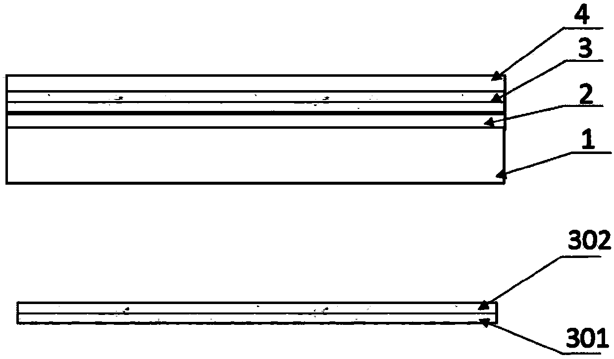
[0041] figure 2 is a schematic structural diagram of the flexible piezoelectric transducer provided in this embodiment. like figure 2 As shown, in this embodiment, the flexible PVDF piezoelectric film is covered on the flexible substrate, and the material of the flexible substrate is a material with strong deformation capacity and ductility, preferably: ethylene phthalate (PET) , polycarbonate (PC) or polyimide (PI). Specifically, the flexible piezoel...

example 1

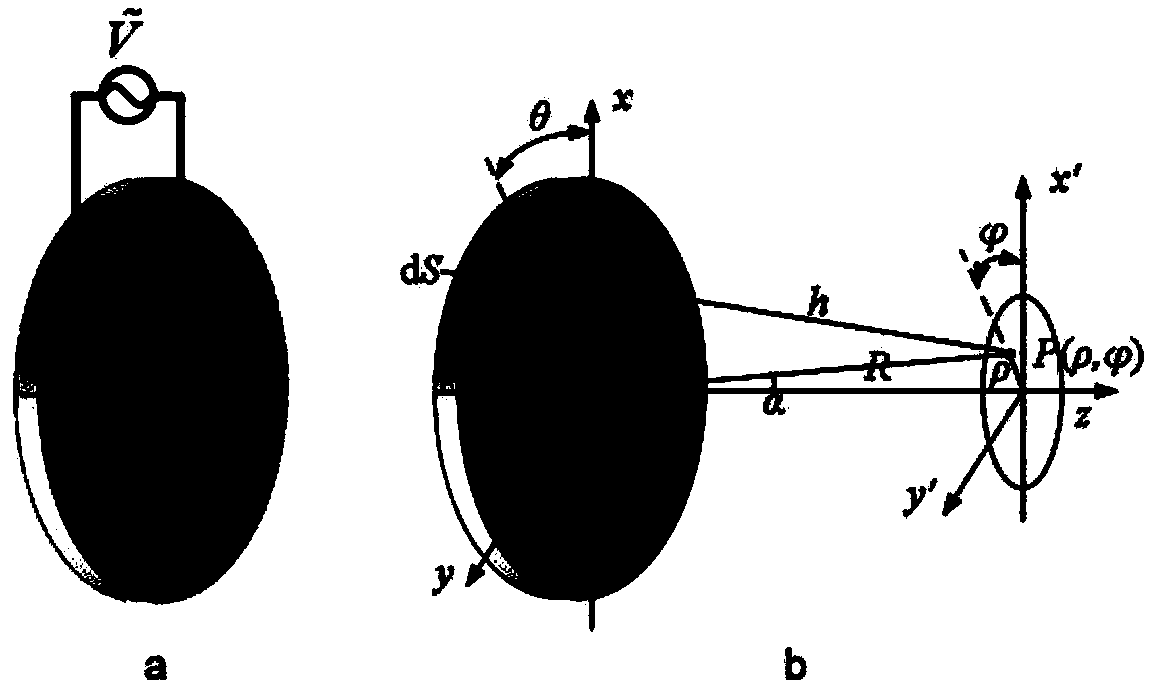
[0057] When there are multiple equiangular spiral electrode strips, taking 4 spiral arms as an example, the initial inner diameter a 1 =13.8mm, initial outer diameter a 2 =14.85mm, the azimuth coefficients of the spiral electrodes corresponding to the topological charges l being 1, 2, 3 and 4 are respectively b 1 =0.0225,b 2 =0.0451,b 3 =0.0676,b 4 =0.0902, the end angles of the azimuth angles are θ 1 =12π, θ 2 =6π, θ 3 = 4π, θ 4 = 3π. At this time, the minimum width of the equiangular spiral electrode strip is d min = 1mm, the maximum width of the equiangular spiral electrode strip is d max =2.47mm, after applying the sinusoidal excitation signal of the same frequency and phase, it can generate 305kHz~750kHz vortex sound wave.

example 2

[0059] When the equiangular spiral electrode strip is a single strip, the initial inner diameter is 13.8mm, the initial outer diameter is 14.85mm, the azimuth angle coefficient b=0.0225, the azimuth angle θ rotates from 0 to 12π, and 425kHz can be generated after applying a sinusoidal excitation signal Vortex sound waves.

[0060] Both the flexible substrate and the PVDF piezoelectric film can be bent under different conditions. see Figure 4 , which shows a schematic diagram of the deformation of the flexible piezoelectric transducer under different force conditions. Figure 5 Shows the zoom spot depth of the flexible substrate and the PVDF piezoelectric film in the change of force bending and extension. The flexible substrate provided with the PVDF piezoelectric film is concave spherical in use. Change, the flexible substrate changes the radius of curvature through bending deformation, and then realizes the variable focal spot depth. Figure 5 R in SR is the curvature of...


PUM


Abstract

The present application relates to a flexible piezoelectric transducer and a system, the flexible piezoelectric transducer comprises: a flexible substrate which is circular in a first state and concave spherical in a second state, and which is capable of dynamically changing the radius of curvature by bending deformation; a flexible piezoelectric film layer which is arranged on the flexible substrate, at least one spiral electrode strip is arranged on the upper surface of the flexible piezoelectric film layer, the at least one spiral electrode strip has the same original point, and a fully-coated electrode is arranged on the lower surface of the flexible piezoelectric film layer. According to the flexible piezoelectric transducer and the system, the equipment integration degree is improved; by means of bending deformation of the flexible substrate and the flexible piezoelectric film layer, after phased excitation of acoustic spiral wave beams, the depth of a focal spot can be dynamically changed, the directivity of an emission array element is widened, energy superposition in a focusing area is enhanced, focusing acoustic vortex change is stable, and a long distance can be maintained in the propagation direction.

Description

technical field [0001] The present application relates to the field of acoustic technology, in particular to a flexible piezoelectric transducer and system. Background technique [0002] Acoustic vortex beams with helical phase misalignment have attracted extensive attention in recent years, and their energy and phase distribution make them have great application potential. This technology has very broad application prospects in acoustic detection, imaging or manipulation and capture of tiny particles, especially in the medical field. The non-contact transfer of angular momentum enables acoustic vortex beams to be used as acoustic wrenches; the circular distribution of acoustic power enables them to be used as acoustic tweezers; the multi-order nature of the topological dimension indicates the great importance of channel multiplexing in underwater acoustic communication. potential. Acoustic vortex beams hold promise for the development of acoustic tweezers or acoustic wren...

Claims


Application Information

Patent Timeline
IPC IPC(8): H04R17/00
CPCH04R17/00
Inventor 吕舒晗杜依诺张宝军
Owner 吕舒晗
Learn More