
Two-dimensional MEMS scanning galvanometer laser radar system

A scanning galvanometer and laser radar technology, applied in radio wave measurement systems, instruments, etc., can solve problems such as limiting detection, and achieve the effects of reducing volume, improving detection distance and detection accuracy, and improving signal-to-noise ratio.

Active Publication Date: 2019-11-22
SUZHOU INST OF NANO TECH & NANO BIONICS CHINESE ACEDEMY OF SCI
View PDF8 Cites 20 Cited by
  • Summary
  • Abstract
  • Description
  • Claims
  • Application Information

AI Technical Summary

Problems solved by technology

[0003] The laser radar system mainly has a coaxial optical path for transmitting and receiving and a parallel optical path for transmitting and receiving. The MEMS oscillating mirror is used in the coaxial optical path system for transmitting and receiving the laser radar. Since the small surface of the MEMS micromirror will limit the aperture of the receiving system, thus limiting the laser radar system to Detection of distant targets

Method used


Image

  • Two-dimensional MEMS scanning galvanometer laser radar system
  • Two-dimensional MEMS scanning galvanometer laser radar system
  • Two-dimensional MEMS scanning galvanometer laser radar system

Examples


Embodiment 1

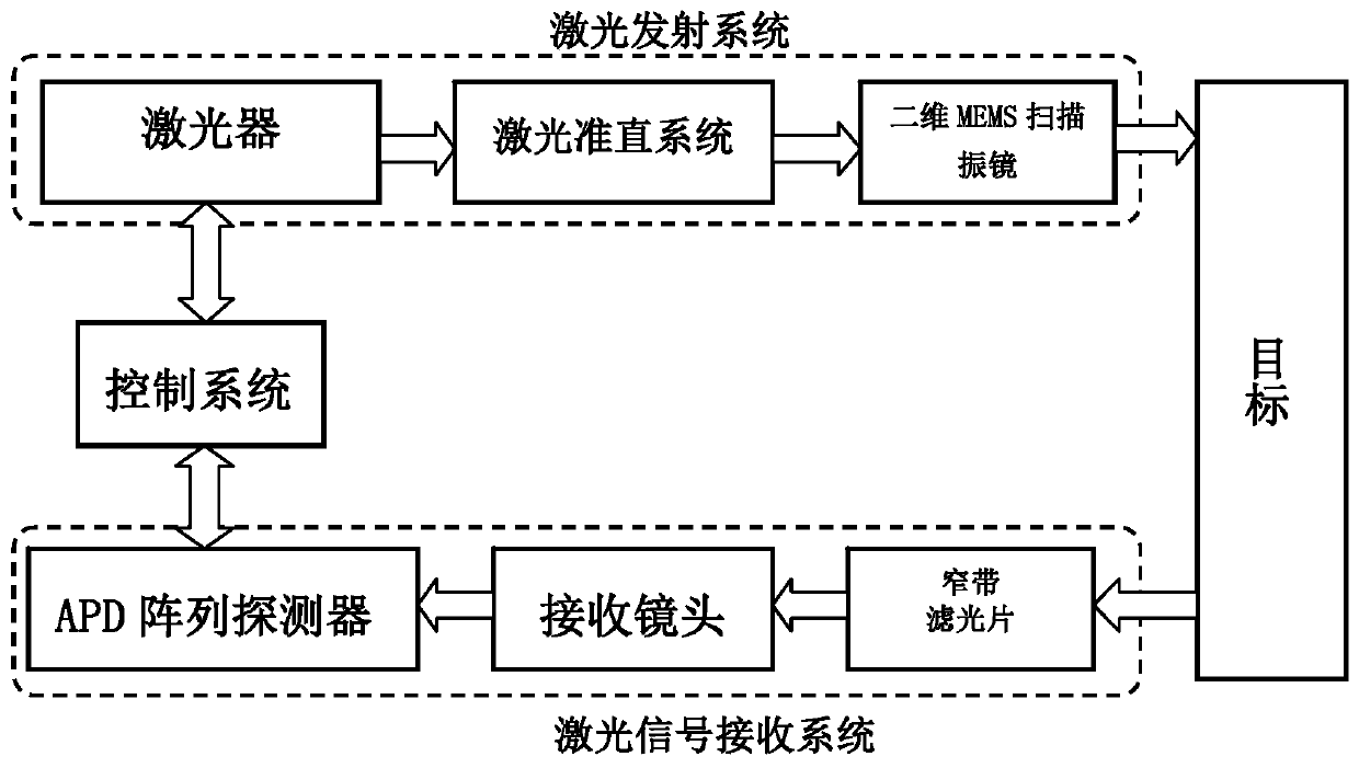
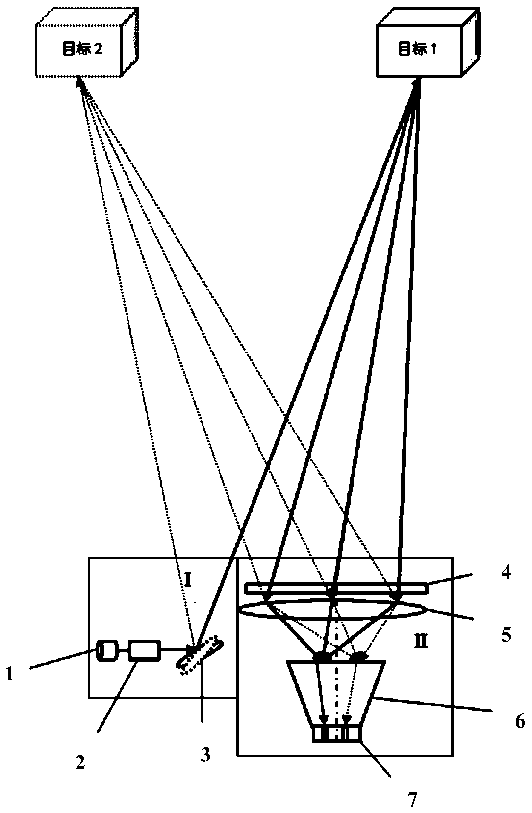
[0040] A two-dimensional MEMS scanning galvanometer lidar system, such as figure 1 , figure 2 As shown, it includes a laser emitting system, a control system, and a laser signal receiving system; in the direction of the optical axis along the light propagation direction, the laser emitting system is sequentially set as: laser 1, laser alignment system 2, two-dimensional MEMS scanning Galvanometer 3; such as Figure 5 As shown, the described laser signal receiving system is sequentially arranged from the object side to the image side as follows: narrow-band filter 4, large relative aperture optical lens 5, image transmission fiber optic cone 6, APD array detector 7; large relative aperture optical lens The lens and the image transmission fiber light cone form the receiving lens; the image transmission fiber light cone is a tapered structure, the large end of the aperture is the incident end face 8, and the small end of the aperture is the exit end face 9; the image transmissi...


PUM


Abstract

The invention, which belongs to the field of laser radar detection, proposes a two-dimensional MEMS scanning galvanometer laser radar system, thereby extending a receiving field of view and increasinga signal-to-noise ratio. A two-dimensional MEMS scanning galvanometer is a scanning mechanism. A control system controls the laser to emit high-frequency pulsed laser; the returned laser signal lightpasses through a filter and a large relative aperture optical lens successively and then is imaged on the incident end face of an image transmission fiber light cone; the image transmission fiber light cone transmits to the surface of an APD array detector. The image transmission fiber light cone is formed by arranging a cone-shaped optical fiber bundle. The APD array detector selects a corresponding APD detector unit to collect signals according to scanning angle of the two-dimensional MEMS scanning galvanometer and the position of a light spot outputted by corresponding echo light at the image transmission fiber light cone. Therefore, , when the caliber, focal length, and detector area of the receiving optical system are certain, the field of view of the MEMS laser radar can be extended, the interference of the ambient background light on the system can be reduced, and the signal-to-noise ratio of the signal receiving can be improved.

Description

technical field [0001] The invention belongs to the field of laser radar detection, and in particular relates to a two-dimensional MEMS scanning vibrating mirror laser radar system. Background technique [0002] LiDAR can be roughly divided into mechanical LiDAR and solid-state LiDAR. At present, the lidar with a large receiving field of view adopts a mechanical rotation structure, uses a laser light source and a turntable mechanical scanning system to scan the measured object point by point, and restores the data into the distance image of the target in sequence. When performing three-dimensional scanning, two-dimensional scanning is required, the structure is complex, the cost is high, and the resolution is not high. Applying MEMS micro-electro-mechanical systems to lidar can directly integrate a very compact micro-vibration mirror on a silicon-based chip, and the micro-vibration mirror that can rotate in two dimensions reflects the light of the laser to realize scanning....

Claims


Application Information

Patent Timeline
Patent Type & Authority Applications(China)
IPC IPC(8): G01S7/481
CPCG01S7/4817Y02A90/10
Inventor 吴东岷王懋范娜娜
Owner SUZHOU INST OF NANO TECH & NANO BIONICS CHINESE ACEDEMY OF SCI
Learn More