A continuous composite molding lightweight photovoltaic module and its continuous composite molding equipment

A photovoltaic module and composite molding technology, applied in photovoltaic power generation, electrical components, semiconductor devices, etc., can solve the problems of photovoltaic module product effect, inability to promote and apply on a large scale, deformation and creeping, etc., to avoid high bursting problems, flexible layout Variety, no grounding effect

Active Publication Date: 2021-08-10
SUNMAN (ZHENJIANG) CO LTD
View PDF6 Cites 17 Cited by
  • Summary
  • Abstract
  • Description
  • Claims
  • Application Information

AI Technical Summary

Problems solved by technology

[0010] Although these comparative documents propose the design of using the structure of the substrate layer and the honeycomb core layer to directly replace the backplane and the aluminum frame, these technologies all use an adhesive layer or an adhesive film layer to realize the connection between the substrate layer and the honeycomb core layer. Connection and compounding, however, as mentioned in Reference 1, the composite structure applied to the photovoltaic backsheet will cause problems such as bubbling, degumming, deformation and creep during subsequent lamination, which will seriously affect the effect of the final photovoltaic module product. Moreover, since the conventional idea of ​​photovoltaic packaging technology is to use adhesive film layers to connect and compound functional material layers and to use adhesives for connection and compounding, it is also a conventional molding and compounding process for conventional honeycomb panels or foamed panels, which also leads to problems such as The light-weight photovoltaic module solutions in the above-mentioned comparative documents 1-3 are all based on the technical development of the substrate layer and the honeycomb core layer and then compounding them through traditional adhesive films or adhesives, and the applicant found after intensive search that , in order to solve the problems of these composite structures, either set the vent structure, or choose to directly sacrifice its composite effect
Therefore, the current application of these technologies is basically at the laboratory certification or small-scale test level, and it is impossible to truly implement large-scale promotion and application.

Method used


Image

  • A continuous composite molding lightweight photovoltaic module and its continuous composite molding equipment
  • A continuous composite molding lightweight photovoltaic module and its continuous composite molding equipment
  • A continuous composite molding lightweight photovoltaic module and its continuous composite molding equipment

Examples


Embodiment 1

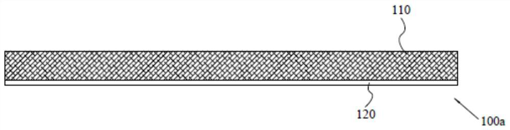
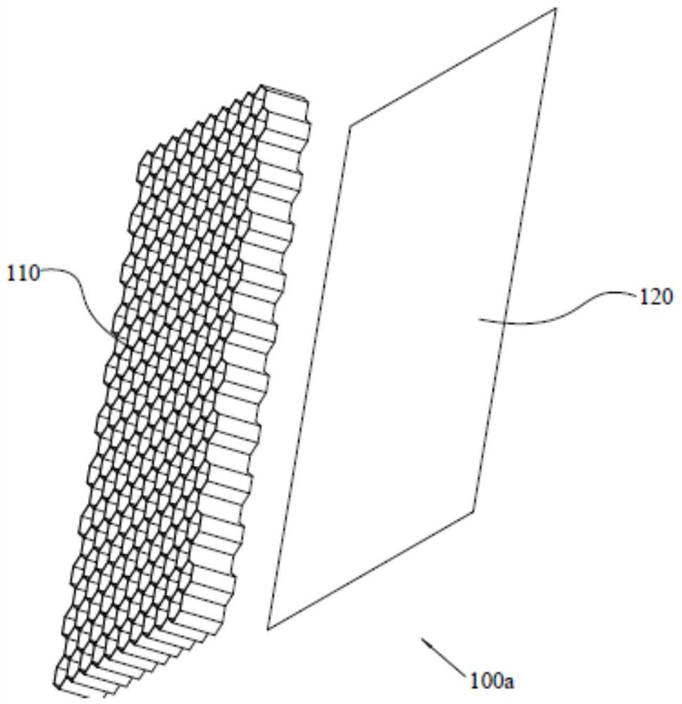
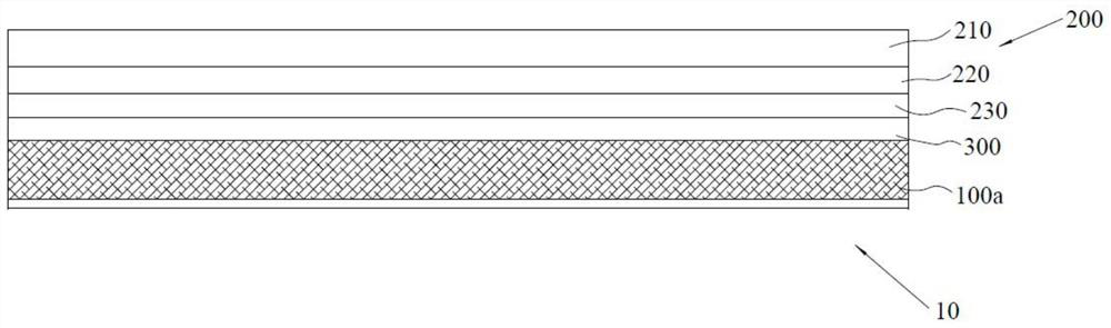
[0050] Example 1: see image 3 As shown, a continuous composite molding lightweight photovoltaic module 10 includes a photovoltaic laminate 200 and a lightweight photovoltaic backplane 100a, and a hot melt adhesive film layer is provided between the photovoltaic laminate 200 and the lightweight photovoltaic backplane 100a 300. The photovoltaic laminate 200 includes a front flexible encapsulation layer 210, a battery sheet layer 220, and a back flexible encapsulation layer 230 that are laminated and packaged as one. Specifically, preferably, in this embodiment, the front flexible encapsulation layer includes a flexible The front composite layer and the front adhesive film layer prepared from composite materials, the composite layer specifically adopts acrylic thermosetting powder coating composite fiber cloth, and its specific technical scheme can be directly referred to CN201610685536.0; the back flexible packaging layer 230 includes EVA adhesive film layer and PET , and other...

Embodiment 2

[0059]Embodiment 2: The rest of the technical solution of this embodiment 2 is the same as that of embodiment 1, the only difference is that: in this embodiment 2, the lightweight photovoltaic backplane adopts the lightweight photovoltaic backplane of Reference 2.

Embodiment 3

[0060] Embodiment 3: The rest of the technical solution of this embodiment 2 is the same as that of embodiment 1, the only difference is that: in this embodiment 3, the lightweight photovoltaic backplane adopts the lightweight photovoltaic backplane of Reference 3.


PUM

PropertyMeasurementUnit
thicknessaaaaaaaaaa
thicknessaaaaaaaaaa
thicknessaaaaaaaaaa

Abstract

The invention discloses a continuous composite molding lightweight photovoltaic module, which includes a photovoltaic laminate and a lightweight photovoltaic backplane. The photovoltaic laminate includes a front flexible packaging layer, a battery sheet layer, and a back flexible packaging that are laminated and packaged as one. layer, the lightweight photovoltaic backplane includes at least a thermoplastic core layer in the shape of a honeycomb or porous foam and a first thermoplastic substrate layer, and the photovoltaic laminate and the lightweight photovoltaic backplane are composited into one body through a continuous composite molding process; The invention also discloses continuous composite molding equipment; the invention also has the advantages of light weight, safety and reliability, frameless design is not easy to accumulate dust and does not need to be grounded, and its layout can be flexible and changeable, avoiding the high burst problem of traditional double glass components, Moreover, the present invention will not cause problems such as bubbling, degumming, deformation and creep under the lightweight photovoltaic backplane scheme using the adhesive film layer structure, and will not be limited by the thickness of the light photovoltaic backplane, which fully meets the requirements of photovoltaic standards. , can realize real-scale promotion and application.

Description

technical field [0001] The invention belongs to the photovoltaic encapsulation technology, and in particular relates to a continuously composite-molded lightweight photovoltaic module, and the invention also relates to a continuous composite-molded equipment used in the continuously composite-molded lightweight photovoltaic module. Background technique [0002] Reliability, safety and low cost are requirements that any energy product must meet at the same time. In the past few decades, the photovoltaic industry has reduced the cost of photovoltaic products by as much as 300 times in the past 40 years through continuous and high-quality research and development to improve photoelectric conversion efficiency, supply chain and localization and automation of production equipment. Of course, over the past few decades, the cost of photovoltaic cells has been significantly and effectively reduced to the extreme. Both the limit of conversion efficiency and the scale effect of produc...

Claims


Application Information

Patent Timeline
Patent Type & Authority Patents(China)
IPC IPC(8): H01L31/048H01L31/049H01L31/18
CPCH01L31/0481H01L31/1876H01L31/049Y02E10/50Y02P70/50
Inventor 王伟力练成荣施正荣
Owner SUNMAN (ZHENJIANG) CO LTD
Why Eureka
Try Eureka