Non-flange waveguide connection structure and design method

A connection structure, flangeless technology, applied in the microwave field, can solve the problems of electromagnetic leakage, difficult to predict and guarantee electromagnetic transmission performance, unfavorable flexible disassembly and assembly, etc., to achieve good assembly tolerance performance, reliable electromagnetic transmission performance, and reduce volume. and the effect of weight

Inactive Publication Date: 2019-11-22
XIAN INSTITUE OF SPACE RADIO TECH
View PDF4 Cites 9 Cited by
  • Summary
  • Abstract
  • Description
  • Claims
  • Application Information

AI Technical Summary

Problems solved by technology

If the consistency of the welding process is difficult to guarantee, the electromagnetic transmission performance of the welded flangeless waveguide connection is difficult to predict and guarantee
On the other hand, welding is an irreversible process. Once the welding is completed, the structure and position of the waveguide cannot be changed, which is not conducive to the flexible disassembly and assembly of various components and components in the system, and is not conducive to the overall design and flexible layout of the system. low mechanical stability
If the waveguide direct plug-in design is adopted, due to the existence of machining errors and roughness, ideal electrical contact cannot be formed in practice, and there will be air gaps between the plug-in contact surfaces, causing electromagnetic leakage and affecting electromagnetic transmission performance

Method used


Image

  • Non-flange waveguide connection structure and design method
  • Non-flange waveguide connection structure and design method
  • Non-flange waveguide connection structure and design method

Examples


Embodiment

[0058] Take the realization of the flangeless connection of the Ku frequency band BJ120 (WR75) waveguide (working bandwidth 9.84GHz~15GHz) as an example to illustrate the specific implementation process of the present invention:

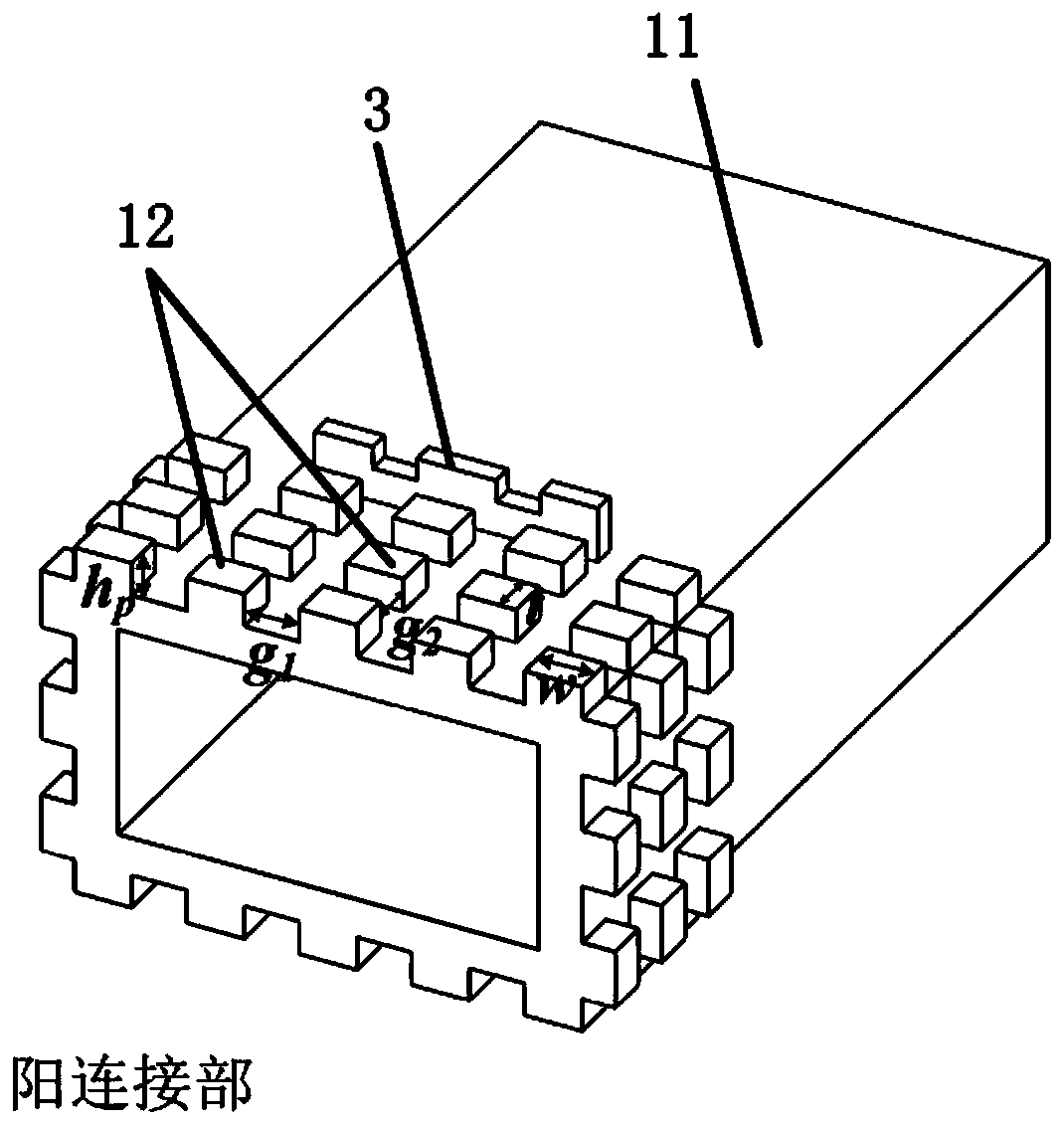
[0059] (1) Establish the simulation model of a single metal bump in the periodic metal bump array 12 in the electromagnetic simulation program, such as Figure 5 Said, the height of each metal protrusion in the periodic metal protrusion array 12 is h p , the width is w, and the thickness is t; the lateral distance between adjacent metal protrusions is g 1 , the vertical spacing is g 2 , the air gap between the metal convex body and the inner surface of the enlarged cavity structure 22 due to tolerance and machining error is h a , set the initial value of the size parameter, set the periodic boundary condition, and set the eigensolution mode.

[0060] (2) According to the actual tolerance and machining error, set the air gap h a The value range is...


PUM


Abstract

The invention discloses a non-flange waveguide connecting structure, which comprises a male connecting part and a female connecting part, and is characterized in that the male connecting part comprises a first waveguide and a periodic metal convex body array, wherein the periodic metal convex body array is arranged on the peripheral surface of the outer wall of the tail end of the first waveguide,and a plurality of metal convex bodies are respectively and uniformly arranged according to a periodic layout rule; the female connecting part comprises a second waveguide and an expanded cavity structure; the expanded cavity structure is arranged at the tail end of the second waveguide, and the end, provided with the periodic metal convex body array, of the male connecting part is inserted intothe expanded cavity structure of the female connecting part to form the whole non-flange waveguide connecting structure. Compared with a traditional waveguide flange, the non-flange waveguide connection structure provided by the invention has the advantages that the size is greatly reduced, the structure layout is more facilitated, and more convenient and flexible assembly can be realized throughthe pluggable design.

Description

technical field [0001] The invention relates to a flangeless waveguide connection structure and a design method, which can be used in various microwave components and system connection structures, and belongs to the field of microwave technology. Background technique [0002] Waveguide is an important transmission line for transmitting microwave signals, and the most commonly used one is a rectangular waveguide, including a rectangular metal tube and a flange. Vertical, centered, waveguides with different rectangular cross-sections and flanges with different sizes for different frequency bands. Due to the advantages of low insertion loss and high power capacity, waveguide transmission lines are widely used in satellite payload systems. Due to the limitation of the space of the satellite payload platform and the carrying capacity of the vehicle, volume and weight have become important considerations in payload design. A large number of connection structures are required in ...

Claims


Application Information

Patent Timeline
Patent Type & Authority Applications(China)
IPC IPC(8): H01P1/04H01P11/00G06F17/50
CPCH01P1/042H01P11/00
Inventor 陈翔孙冬全崔万照李小军殷康贺永宁
Owner XIAN INSTITUE OF SPACE RADIO TECH
Why Eureka
Try Eureka