
Micro-flow green high-energy monopropellant thruster structure

A thruster and micro-flow technology, which is applied in the direction of jet propulsion devices, machines/engines, space vehicle propulsion system devices, etc., can solve problems such as failure to meet the use requirements, harsh thermal environment of the thruster, and small working flow of the thruster, etc. Achieve the effects of increasing heat transfer resistance, compact installation structure, and weakening conduction

Active Publication Date: 2019-11-26
BEIJING INST OF CONTROL ENG
View PDF6 Cites 5 Cited by
  • Summary
  • Abstract
  • Description
  • Claims
  • Application Information

AI Technical Summary

Problems solved by technology

[0002] With the development of green high-energy single-element propulsion technology, such as ADN propulsion technology, the performance of the thruster has been greatly improved, but at the same time, due to the increase in the temperature of the thrust chamber, the thermal environment in which the thruster is located is even worse, which affects the thruster’s performance. The design brings great challenges. At the same time, for small-thrust single-element thrusters, the working flow of the thruster is small, which makes the thruster more sensitive to the temperature rise of the thrust chamber, which will cause the propulsion in the capillary of the thruster injector. The agent produces two-phase flow, forming an air block, resulting in unstable thrust, which cannot meet the requirements of use

Method used


Image

  • Micro-flow green high-energy monopropellant thruster structure
  • Micro-flow green high-energy monopropellant thruster structure
  • Micro-flow green high-energy monopropellant thruster structure

Examples


Embodiment Construction

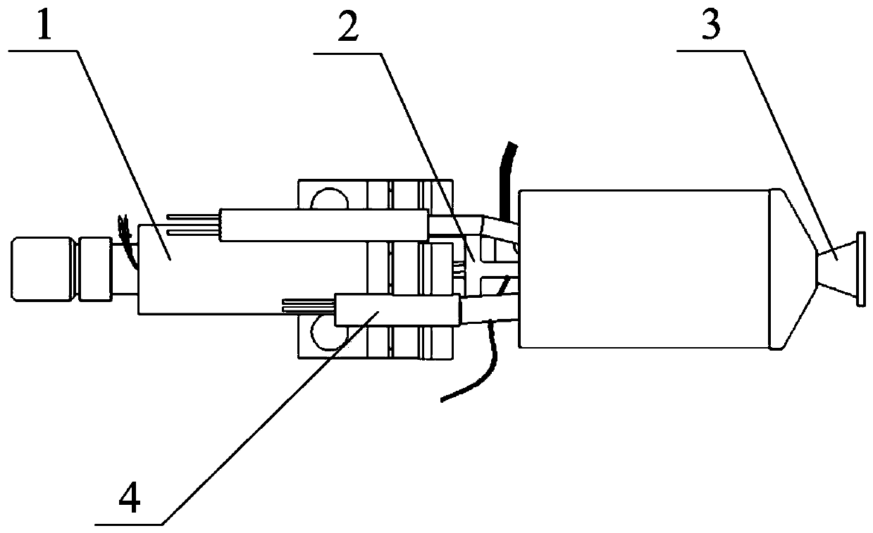
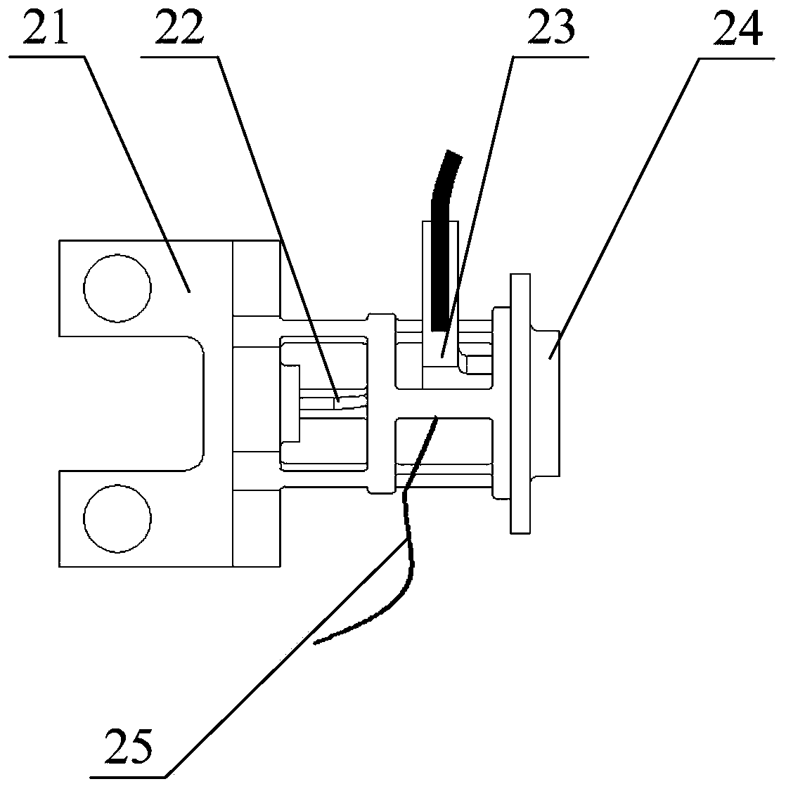
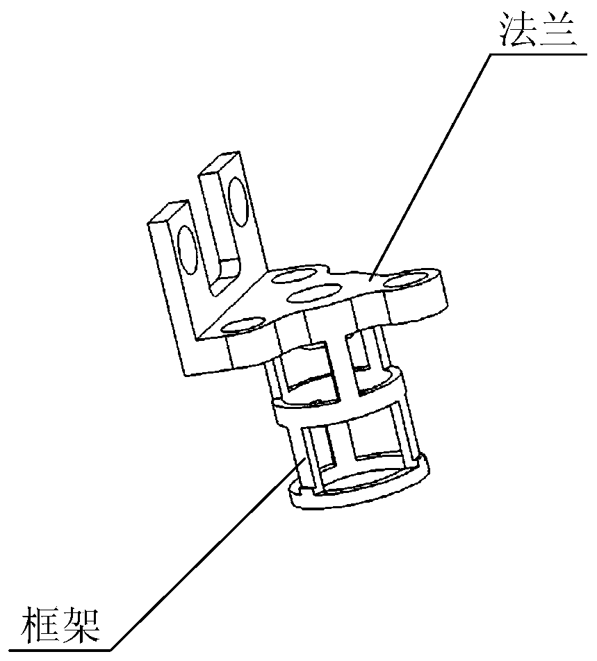
[0025] The invention relates to a micro-flow green high-energy single-unit thruster structure, comprising a miniature solenoid valve (1), an injector (2), a thrust chamber (3) and a thermal control assembly (4); a miniature solenoid valve (1) The outlet is connected to the inlet of the injector (2) for on-off management of the circulation of the propellant; the outlet of the injector (2) is connected to the inlet of the thrust chamber (3), and the flange frame (21), capillary (22) ), heat conduction sheet (23), front chamber (24) and capillary heat conduction wire (25), injector (2) flange frame (21) realizes blocking thrust chamber (3) heat to miniature electromagnetic valve ( 1) direction conduction, the heat conduction sheet (23) reduces the heat conduction of the thrust chamber (3) to the capillary (22), and the capillary heat conduction wire (25) is installed on the capillary (22) close to the thrust chamber (3) side, lowering the capillary (22) ) temperature, capillary (...


PUM


Abstract

The invention relates to a micro-flow green high-energy monopropellant thruster structure. The catalytic decomposition of a propellant is realized under the action of a catalyst in a catalysis bed, and the propellant is further combusted in a combustion chamber and then is sprayed out by a spray pipe to generate thrust; and a heat control assembly is installed on the catalysis bed in a thrust chamber, and temperature control and monitoring are carried out on the catalysis bed. The micro-flow green high-energy mono propellant thruster structure has the advantages that the temperature of a capillary pipe is regulated and controlled through a heat conduction sheet, a capillary pipe heat conduction wire and the like, the two-phase flow, generated in the capillary pipe, of the propellant is inhibited under the micro-flow, and the stable operation of a micro-flow green high-energy monopropellant thruster is realized. The micro-flow green high-energy monopropellant thrust has the characteristics of being high in specific impulse, green, non-toxic, light in mass, capable of being pre-packaged and the like, the required force or torque is provided for maneuvering, fast response and the likeof a micro-nano satellite, and the application space of the micro-nano satellite is greatly expanded.

Description

technical field [0001] The invention relates to a micro-flow green high-energy single-unit thruster structure, which belongs to the field of propulsion technology. Background technique [0002] With the development of green high-energy single-element propulsion technology, such as ADN propulsion technology, the performance of the thruster has been greatly improved, but at the same time, due to the increase in the temperature of the thrust chamber, the thermal environment in which the thruster is located is even worse, which affects the thruster’s performance. The design brings great challenges. At the same time, for small-thrust single-element thrusters, the working flow of the thruster is small, which makes the thruster more sensitive to the temperature rise of the thrust chamber, which will cause the propulsion in the capillary of the thruster injector. The agent produces a two-phase flow, forming an air block, resulting in unstable thrust, which cannot meet the applicatio...

Claims


Application Information

Patent Timeline
IPC IPC(8): F02K9/42B64G1/40
CPCB64G1/40F02K9/42F02K9/44F02K9/52F02K9/60F02K9/62
Inventor 刘旭辉付拓取张伟高晨光官长斌刘瀛龙王梦李永平沈岩陈君王平杨蕊赵春阳苏高世吴耀武周磊刘全成甄利鹏庚喜慧赵立伟周旭冉
Owner BEIJING INST OF CONTROL ENG
Learn More