A plate evaporator

A plate evaporator and substrate technology, applied in evaporator accessories, evaporation, evaporator/condenser, etc., can solve the problems of high cutting cost, high equipment investment cost, and increased equipment control cost.

Active Publication Date: 2021-04-30
江苏远卓设备制造有限公司
View PDF10 Cites 2 Cited by
  • Summary
  • Abstract
  • Description
  • Claims
  • Application Information

AI Technical Summary

Problems solved by technology

The production line has a high degree of automation, but the production line includes two parallel production lines, and the equipment investment cost is high, especially in the final stamping part of the two heat exchange fins. The machine punches out the holes, but in fact the heat exchange fins produced by the two production lines must ensure that they match each other very high, which requires extremely high production accuracy, which undoubtedly increases the control cost of the equipment. The plate package can only produce heat exchangers without distributors. If distributors are required, distributor gaskets must be installed manually, which is not only troublesome and costly, but distributors are standard equipment for refrigerant evaporators.

Method used


Image

  • A plate evaporator
  • A plate evaporator
  • A plate evaporator

Examples


Embodiment 1

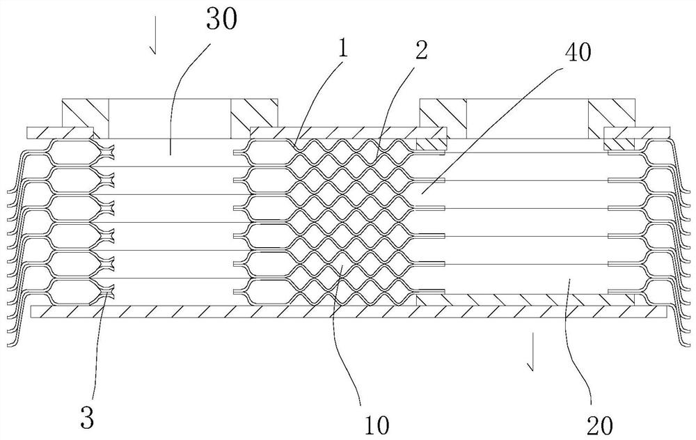
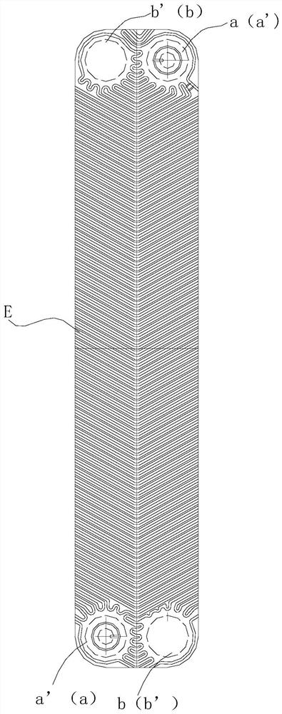
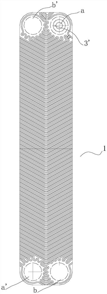
[0040]The main structure of the plate evaporator of the present embodiment is a series of heat exchange plates that are laminated together by the first heat exchange sheet 1 and the second heat exchange sheet 2, and the first heat exchange sheet 1 and the second heat exchange sheet 2 are between Formation of mutually interlocation, isolating heat transfer flow paths, respectively, isolated, respectively. In the first, the first surface 6 of the second heat transfer plate is provided with four corner apertures, including the first in-liquid holes A and the first liquid holes A 'for the flow through flow flow out of the evaporation agent for heat transfer agent. The second liquid hole B and the second liquid hole B 'of the flow flowing out corresponds to the same corner aperture on the thickness direction corresponding to the first in liquid passage 30, the first liquid passage, the first Different liquid passages and second liquid passage 20. The same corner aperture is concave or co...

Embodiment 2

[0044]Based on the plate evaporator according to Example 1, the first and second heat transfer plates may be respectively punched by the center symmetrical same substrate, and the punching means including the first intake / outlet and the second into / outlet. Synchronous stamping operation of a total of four corner apertures within the same. When the second liquid hole and the second liquid hole of the first embodiment are the same, the first and second heat exchange plates may further be further rushing the second into the same substrate, the same substrate of the liquid holes, respectively. Synchronous rolled out the first in / outlet.

[0045]The preparation of the above-mentioned plate evaporator is achieved on a production line.

[0046](1) The continuous feed volume of the copper foil and substrate metal material is prepared;

[0047](2) Copper foil feed: to the copper foil punching punch, in the calculated position punched hole, the left-blank portion covers the recess of the first i...


PUM


Abstract

The invention relates to a plate type evaporator, which comprises a series of heat exchange plates stacked at intervals between the first heat exchange fins and the second heat exchange fins (2) to form an interlaced , isolated heat exchange channels; the first surface (6) of the first and second heat exchange plates has a heat exchange area (E); the first surface (6) is respectively provided with four corner holes corresponding to the cold / heat medium Liquid inlet channel or liquid outlet channel; at least one groove (3') is provided on the edge of the first liquid inlet hole (a) for cold medium inlet in the four corner holes, and the groove (3') starts from the first inlet The edge of the liquid hole (a) extends all the way to the heat exchange channel; the first surface (6) is centrosymmetric except for the four corner holes, but the arrangement of the center points of the four corner holes also satisfies centrosymmetry; the first and second heat exchange The plates are punched separately from the same substrate. Copper foil is applied on the first surface of each heat exchange plate, the heat exchange plates are stacked in sequence, and the copper foil is heated to melt to form a permanent bond between the first and second heat exchange plates.

Description

Technical field[0001]The present invention relates to a plate heat exchanger in combination with a multilayer heat exchange plate, and more particularly to a plate evaporator that is permanently bonded together by multilayer heat exchange plates.Background technique[0002]The plate heat exchanger is the most commonly used heat exchanger in the field of cooling and heat, such as air conditioning, heat pump heat, etc., in two interleaved and interlaced flow paths, the evaporation of the refrigerant is discharged during the condensation process. A large amount of heat, refrigeration or heating of the second fluid such as water. The plate evaporator is the most ideal equipment for the heat exchange of liquid-steam. It has the advantages of high heat exchange efficiency, small heat loss, compact structure, small area, and long service life. The plate evaporator is often also divided into detachable and non-detachable, and detachable mainly consists of a certain number of heat exchanger, s...

Claims


Application Information

Patent Timeline
Patent Type & Authority Patents(China)
IPC IPC(8): F25B39/02
CPCB01D1/221B01D1/30
Inventor 缪君明周浩军
Owner 江苏远卓设备制造有限公司
Why Eureka
Try Eureka