Electrified railway in-phase power supply comprehensive compensation device and comprehensive compensation method thereof

An electrified railway, comprehensive compensation technology, applied in circuit devices, electrical components, reactive power compensation, etc., can solve problems such as three-phase voltage imbalance, and achieve the effect of saving floor space, easy implementation, and simple results

Pending Publication Date: 2019-11-26
SOUTHWEST JIAOTONG UNIV
View PDF0 Cites 10 Cited by
  • Summary
  • Abstract
  • Description
  • Claims
  • Application Information

AI Technical Summary

Problems solved by technology

[0005] The purpose of the present invention is to provide a comprehensive compensation device for electrified railway in-phase power supply, which can effectively solve the influence of AC electrified railway on the unbalanced three-phase voltage at the common connection point, and at the same time, it does not bring new power quality problems

Method used


Image

  • Electrified railway in-phase power supply comprehensive compensation device and comprehensive compensation method thereof
  • Electrified railway in-phase power supply comprehensive compensation device and comprehensive compensation method thereof
  • Electrified railway in-phase power supply comprehensive compensation device and comprehensive compensation method thereof

Examples


Embodiment 1

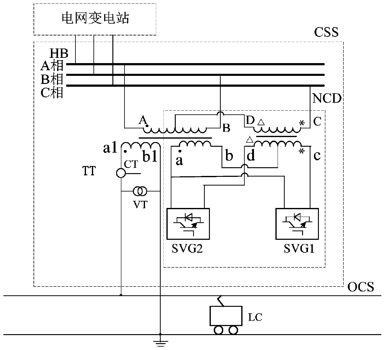
[0032] Such as figure 1 As shown, the embodiment of the present invention provides one of the topological structures: a schematic diagram of an integrated compensation device for in-phase power supply of an electrified railway in two-port compensation mode, including a three-phase high-voltage bus HB connected to a grid substation and a primary side connected to the three-phase high-voltage bus HB The traction-compensation transformer TT, the negative sequence compensation device NCD and the measurement and control system MCS constitute the co-phase power supply traction substation CSS; the secondary winding a1b1 port of the traction-compensation transformer TT is connected in series with the current transformer CT and then connected to the catenary network OCS, the other side port is connected in parallel with the voltage transformer VT and then grounded; the two-port compensation mode includes the compensation winding ab and the compensation winding of the traction-compensatio...

Embodiment 2

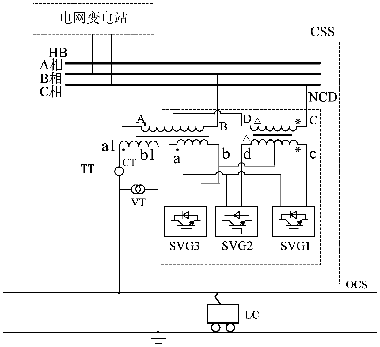
[0035] Such as image 3 As shown, the embodiment of the present invention provides the second topology structure: a schematic diagram of a comprehensive compensation device for in-phase power supply of an electrified railway in three-port compensation mode, including a three-phase high-voltage bus HB connected to a grid substation and a primary side connected to the three-phase high-voltage bus HB The traction-compensation transformer TT, the negative sequence compensation device NCD and the measurement and control system MCS constitute the co-phase power supply traction substation CSS; the secondary winding a1b1 port of the traction-compensation transformer TT is connected to the catenary after the current transformer CT OCS, the other side port is connected in parallel with the voltage transformer VT and then grounded; the three-port compensation mode includes the compensation winding ab and the compensation winding of the traction-compensation transformer whose primary side is...

Embodiment 3

[0038] Such as Figure 5 As shown, the embodiment of the present invention provides a schematic flow chart of a comprehensive compensation method for in-phase power supply of an electrified railway. This embodiment takes the two-port compensation mode comprehensive compensation method as an example. The specific steps of a comprehensive compensation method for in-phase power supply of an electrified railway are as follows:

[0039] (1) Determine the load process of the traction substation through computer simulation technology. According to the load process of the traction substation, compare and select the topological structure of the negative sequence compensation device NCD to determine the final topological structure.

[0040] (2) Take the negative sequence allowable amount S at the common connection point corresponding to the three-phase high voltage bus HB ε As its allowable value of negative sequence power;

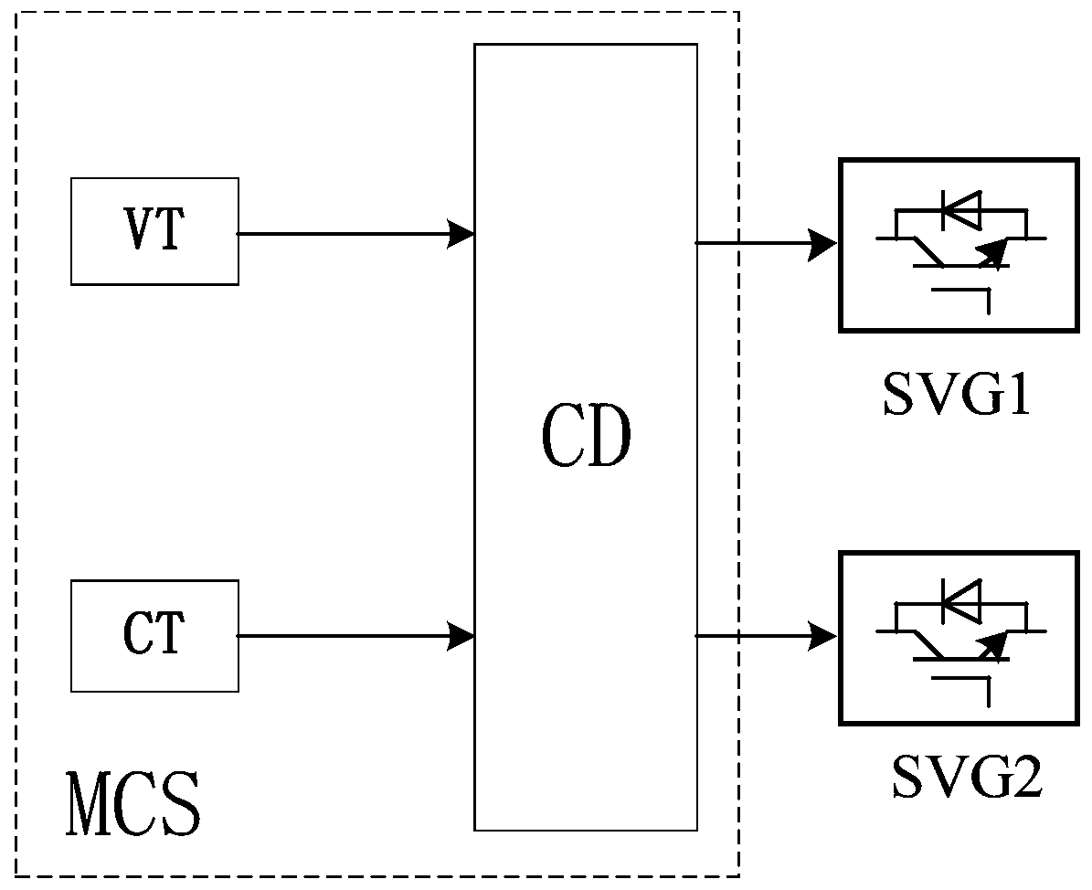
[0041] (3) The controller CD calculates the load S from the voltage a...


PUM


Abstract

The invention discloses an electrified railway in-phase power supply comprehensive compensation device and a comprehensive compensation method thereof, and relates to the technical field of electrified railway in-phase power supply. One of the topological structures is as follows: compensation windings ab and dc of a traction-compensation transformer with the primary side connected with three phases of a three-phase high-voltage bus HB; a reactive compensation unit SVG1 is connected to an ac port of the compensation winding, and the reactive compensation unit SVG2 is connected with an ad portof the compensation winding; a second one of the topological structures is as follows: compensation windings ab and dc of the traction-compensation transformer with the primary side connected with three phases of the three-phase high-voltage bus HB; the reactive compensation unit SVG1 is connected to the ac port of the compensation winding, the reactive compensation unit SVG2 is connected to the ad port of the compensation winding, and a reactive compensation unit SVG3 is connected with an ab port of the compensation winding; and the input end of a controller CD in the measurement and controlsystem MCS is respectively connected with the measurement signal output ends of a voltage transformer VT and a current transformer CT.

Description

Technical field [0001] The invention relates to the technical field of AC electrified railway traction power supply. Background technique [0002] The rapid development of China's high-speed railways further reflects the superiority of China's existing AC electrified railway power frequency single-phase power supply system. The single-phase power frequency system requires that the power supply is divided into phases. In order to reduce the impact of the traction load on the unbalance of the power system, the scheme of alternating phase sequence and split-phase power supply is usually adopted. Practice and theory have shown that electrical phase separation is the weakest link in the traction power supply system. When trains pass through electrical phase separation, problems such as operating overvoltage and train drops may occur. This is to improve transportation quality, ensure operational reliability, and reduce train drops. For issues such as phase separation and improving the...

Claims


Application Information

Patent Timeline
Patent Type & Authority Applications(China)
IPC IPC(8): H02J3/26H02J3/18
CPCH02J3/1842H02J3/26Y02E40/30Y02E40/50
Inventor 王辉李群湛解绍锋易东郭锴吴波高圣夫金安旭
Owner SOUTHWEST JIAOTONG UNIV
Why Eureka
Try Eureka