High-gain boost converter based on active network

A boost converter, active network technology, applied in high-efficiency power electronic conversion, output power conversion device, conversion of DC power input to DC power output, etc., can solve the problem of increasing system complexity and cost, low overall efficiency, Problems such as large loss of power devices, to achieve the effect of small voltage stress, simple control, and improved voltage gain

Inactive Publication Date: 2019-11-26
NANJING UNIV OF SCI & TECH
View PDF5 Cites 4 Cited by
  • Summary
  • Abstract
  • Description
  • Claims
  • Application Information

AI Technical Summary

Problems solved by technology

The traditional Boost converter has the advantages of simple circuit structure and flexible control. It is the most widely used converter at present. However, it can only obtain high voltage gain when working at an extreme duty cycle, and the loss of power devices is large, resulting in low overall efficiency. Low
In order to obtain a high-gain, high-efficiency converter, the current common method uses the converter cascading technology to cascade two or more converters. The voltage gain of the entire converter is the product of the gains of the converters at all levels, but The cascaded Boost converter requires multiple switches and multiple sets of control circuits, which increases the complexity and cost of the system
The introduction of coupled inductance is also an effective method to increase the voltage gain. The working principle of the coupled inductance is similar to that of the transformer. By increasing the winding ratio of the coupled inductance, a larger voltage gain can be obtained, but due to the influence of the leakage inductance of the coupled inductance, it needs to be clamped Circuit suppresses switch off voltage spikes

Method used


Image

  • High-gain boost converter based on active network
  • High-gain boost converter based on active network
  • High-gain boost converter based on active network

Examples


Embodiment Construction

[0012] The solutions of the present invention will be further described below in conjunction with the accompanying drawings and specific embodiments.

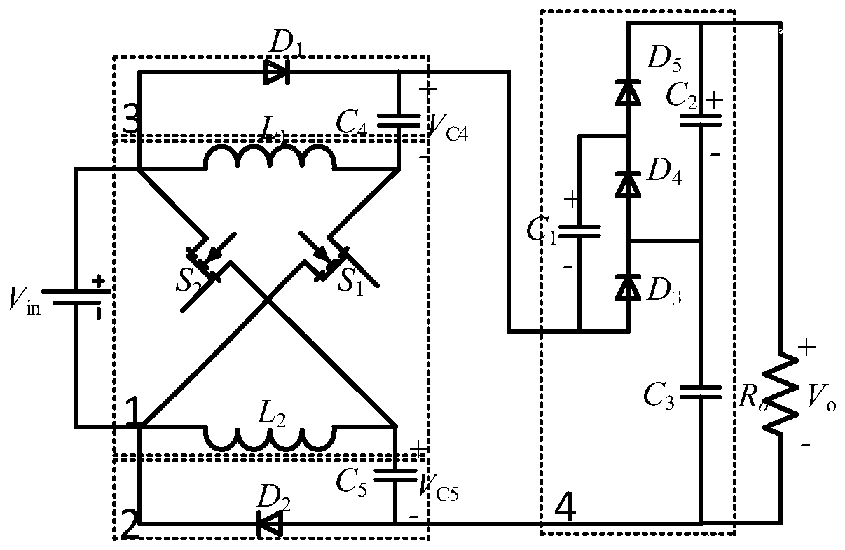
[0013] Such as figure 1 As shown, the active network-based high-gain boost converter consists of an input source V in , load R o , Active network unit 1, switched capacitor units 2-4.

[0014] The active network unit 1 includes a first inductor L 1 , the second inductance L 2 , the first power switch tube S 1 , the second power switch tube S 2 , the first inductance L 1 One end of the first power switch tube S 1 the drain, the first inductor L 1 The other end of the input source V in positive pole of the first power switch tube S 1 The source is connected to the input source V in The negative pole of the second power switch tube S 2 The drain is connected to the input source V in The anode of the source is connected to the second inductance L 2 One end of the second inductor L 2 The other end of the input source ...


PUM


Abstract

The invention discloses a high-gain boost converter based on an active network, belonging to the field of power electronic converters. The high-gain boost converter based on the active network is constituted by combining a switched capacitor unit composed of a capacitor and a diode based on an active network unit composed of a power switch tube and an inductor, which can achieve the effect of increasing the voltage gain by controlling the on-off of the power switch tube and the diode and changing the connection mode of the inductor and capacitor in the circuit. The high-gain boost converter based on the active network has high voltage gain, small switching stress, and small average value of the inductor current, which is helpful to reduce the conduction loss of the switch tube and the diode and reduce the volume of a single inductor, and is suitable for new energy power generation systems such as fuel cells and photovoltaic cells.

Description

technical field [0001] The invention relates to a high-gain boost converter based on an active network, which belongs to the field of power electronic converters. Background technique [0002] With the continuous development of the economy, the consumption of non-renewable fossil energy led by petroleum is increasing day by day, which has brought serious problems to the environment. The new energy power generation system can make full use of nature to generate electricity, solve the energy crisis and environmental problems, and has gradually become a research hotspot around the world. [0003] The new energy power generation system has the characteristics of a low-voltage, high-current output current source, and it is difficult to directly connect to the inverter system for grid-connected operation. A suitable boost converter is needed to raise the output voltage to a level that can meet the needs of the inverter system. The traditional Boost converter has the advantages of...

Claims


Application Information

Patent Timeline
Patent Type & Authority Applications(China)
IPC IPC(8): H02M3/156
CPCH02M3/156H02M1/0048Y02B70/10Y02E10/56
Inventor 裴进戚志东孙琦丁莉田家欣杨晓剑
Owner NANJING UNIV OF SCI & TECH
Why Eureka
Try Eureka