Low-power-consumption EMCCD high-voltage sine driving signal generation circuit

A driving signal generation and low power consumption technology, applied in the electronic field, can solve the problems of complex adjustment of frequency, phase and peak-to-peak value, miniaturization of cameras that cannot meet high readout rates, and limitation of circuit reliability and service life. Simplified production method, low power consumption, and simple structure

Pending Publication Date: 2019-11-26
SUZHOU R&D CENT OF NO 214 RES INST OF CHINA NORTH IND GRP
View PDF3 Cites 1 Cited by
  • Summary
  • Abstract
  • Description
  • Claims
  • Application Information

AI Technical Summary

Problems solved by technology

However, with the increase of voltage and frequency, the power consumption of the square wave drive circuit with push-pull output structure increases sharply, and the power MOS tube heats up seriously. Under the condition of 11MHz and 40V, the power consumption of the circuit with load is close to 3W, which limits Improve the reliability and service life of the circuit
The sine wave circuit composed of DDS and transformer uses FPGA and DAC to generate a sine wave signal of a specific frequency, and then amplifies the sine wave signal through a transformer. The back-end processing requires a series of analog circuits such as filtering, denoising, and amplification. , The adjustment of phase and peak-to-peak value is more complicated
[0003] In the invention patent "EMCCD power drive circuit-CN109413312A", the method of high-speed DAC plus two-stage amplifier is used to realize the high-voltage sinusoidal drive signal of EMCCD, which can effectively reduce the power consumption of the circuit compared with the square wave, and facilitate the adjustment of amplitude and phase. However, due to the characteristics of the circuit itself, it is only suitable for signals with lower frequencies
[0006] Peripheral drive technology for electronically multiplied CCD cameras is currently a research hotspot in the field of low-light and ultra-sensitive imaging at home and abroad. However, due to the power consumption and complexity of high-voltage gain drive circuits, it cannot meet the needs of high readout rates and camera miniaturization. need

Method used


Image

  • Low-power-consumption EMCCD high-voltage sine driving signal generation circuit
  • Low-power-consumption EMCCD high-voltage sine driving signal generation circuit
  • Low-power-consumption EMCCD high-voltage sine driving signal generation circuit

Examples


Embodiment Construction

[0026] The present invention will be further described below in conjunction with the accompanying drawings. The following examples are only used to illustrate the technical solution of the present invention more clearly, but not to limit the protection scope of the present invention.

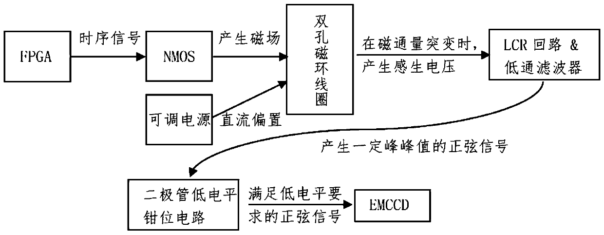
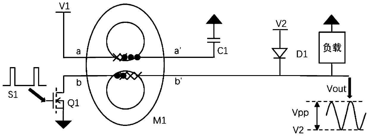
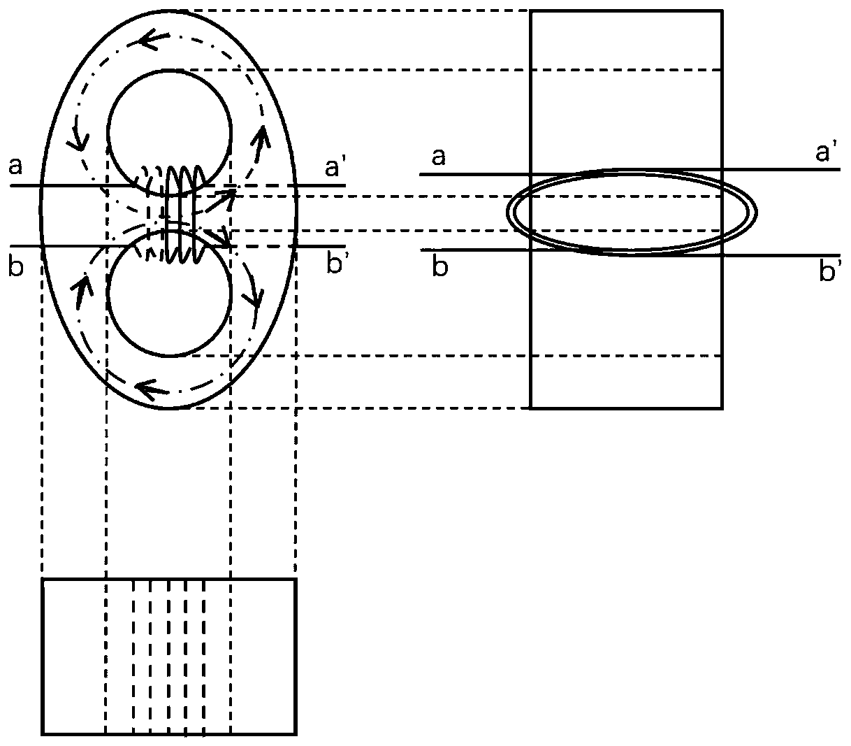
[0027] The invention is a low-power high-voltage sinusoidal drive signal generation circuit, including an enhanced NMOS tube, a double-hole magnetic ring coil, an LCR oscillating circuit and a diode level clamping circuit, such as figure 1 , figure 2 with image 3 shown. The square wave generated by the FPGA unit is connected to the gate of the NMOS tube, the drain of the NMOS tube is connected to the primary coil, and the source of the NMOS tube is grounded; the frequency and phase of the wave signal above the NMOS tube gate are controlled to adjust the frequency and phase of the sine wave. Frequency and phase; the duty cycle of the gate signal of the NMOS and the capacitance C in the LCR c...


PUM


Abstract

The invention discloses a low-power-consumption EMCCD high-voltage sine driving signal generating circuit which comprises a secondary coil, an NMOS tube, an LCR oscillating circuit and a diode. A square wave time sequence signal is input into the grid electrode of the NMOS tube, and the drain electrode of the NMOS tube is connected with the input end of the primary coil; the secondary coil outputend of the secondary coil outputs sine waves through the LCR oscillation loop, and the output sine wave high level is adjusted by controlling the input voltage of the primary loop of the secondary coil; the output sine wave low level is adjusted by adjusting the bias voltage of the diode; the frequency and the phase of the sine wave signal are adjusted by controlling the frequency and the phase ofthe grid driving signal of the NMOS transistor; and the sine wave waveform is adjusted by adjusting the duty ratio of the driving signal and the capacitance C of the LCR loop. Generation of high-voltage sine wave driving signals is simplified, the power consumption is low, the structure is simple, and adjustment is convenient. The low-power-consumption EMCCD high-voltage sine driving signal generating circuit can be used for high-voltage gain driving of an EMCCD device, electron multiplication is achieved, and therefore signal amplification is achieved.

Description

technical field [0001] The invention relates to an EMCCD driving signal generating circuit, which belongs to the field of electronic technology. Background technique [0002] Electron Multiplying Charge Couple Device (EMCCD) adds a gain shift register after the traditional CCD horizontal transfer register, so that the signal charge is impacted and ionized during the transfer process, thereby realizing the amplification of the signal charge. In order to realize the impact ionization of charges, a low-level 4V, high-level 20V-40V adjustable drive signal needs to be applied to the gate of the gain register. At present, the widely used circuit structures include square wave drive circuit with push-pull output, digital frequency synthesizer DDS and sine wave drive circuit composed of transformers. However, with the increase of voltage and frequency, the power consumption of the square wave drive circuit with push-pull output structure increases sharply, and the power MOS tube he...

Claims


Application Information

Patent Timeline
Patent Type & Authority Applications(China)
IPC IPC(8): H04N5/372H03B5/24
CPCH03B5/24H04N25/71
Inventor 沈吉那启跃戴放于洪洲
Owner SUZHOU R&D CENT OF NO 214 RES INST OF CHINA NORTH IND GRP
Why Eureka
Try Eureka