
A pmos device with embedded silicon controlled rectifier and its realization method

A technology for silicon-controlled rectifiers and devices, which is applied in semiconductor devices, electric solid-state devices, electrical components, etc., and can solve the problems of inappropriate anti-static protection design and trigger latch-up effect.

Active Publication Date: 2021-07-16
SHANGHAI HUALI MICROELECTRONICS CORP
View PDF4 Cites 0 Cited by
  • Summary
  • Abstract
  • Description
  • Claims
  • Application Information

AI Technical Summary

Problems solved by technology

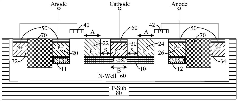
[0006] Table 1 is a comparison table of the hysteresis effect parameters between the existing PMOS embedded silicon controlled rectifier and the traditional GGNMOS and GDPMOS under the 28nm High-K / Metal Gate process. It can be found that the existing embedded silicon-controlled rectifier PMOS can greatly increase the secondary breakdown current of traditional PMOS, even exceeding the secondary breakdown current of traditional GGNMOS, but its maintenance voltage is only about 1.7V, which is lower than the working voltage of 1.8V V, it is easy to trigger the latch-up effect when external disturbances occur. It can be seen that the existing PMOS embedded with silicon controlled rectifiers is not suitable for anti-static protection design, so it is necessary to further improve the existing PMOS devices embedded with silicon controlled rectifiers. Improvement, increase its maintenance voltage Vh, making it suitable for anti-static protection design

Method used


Image

  • A pmos device with embedded silicon controlled rectifier and its realization method
  • A pmos device with embedded silicon controlled rectifier and its realization method
  • A pmos device with embedded silicon controlled rectifier and its realization method

Examples


Embodiment Construction

[0031] The implementation of the present invention is described below through specific examples and in conjunction with the accompanying drawings, and those skilled in the art can easily understand other advantages and effects of the present invention from the content disclosed in this specification. The present invention can also be implemented or applied through other different specific examples, and various modifications and changes can be made to the details in this specification based on different viewpoints and applications without departing from the spirit of the present invention.

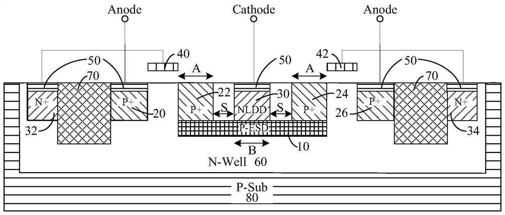
[0032] figure 2 It is a device structure diagram of a preferred embodiment of a PMOS device embedded with a silicon controlled rectifier in the present invention. Such as figure 2As shown, a PMOS device embedded with a silicon-controlled rectifier in the present invention includes: a plurality of shallow trench isolation layers (STI, Shallow Trench Isolation) 70, high-concentration N-typ...


PUM


Abstract

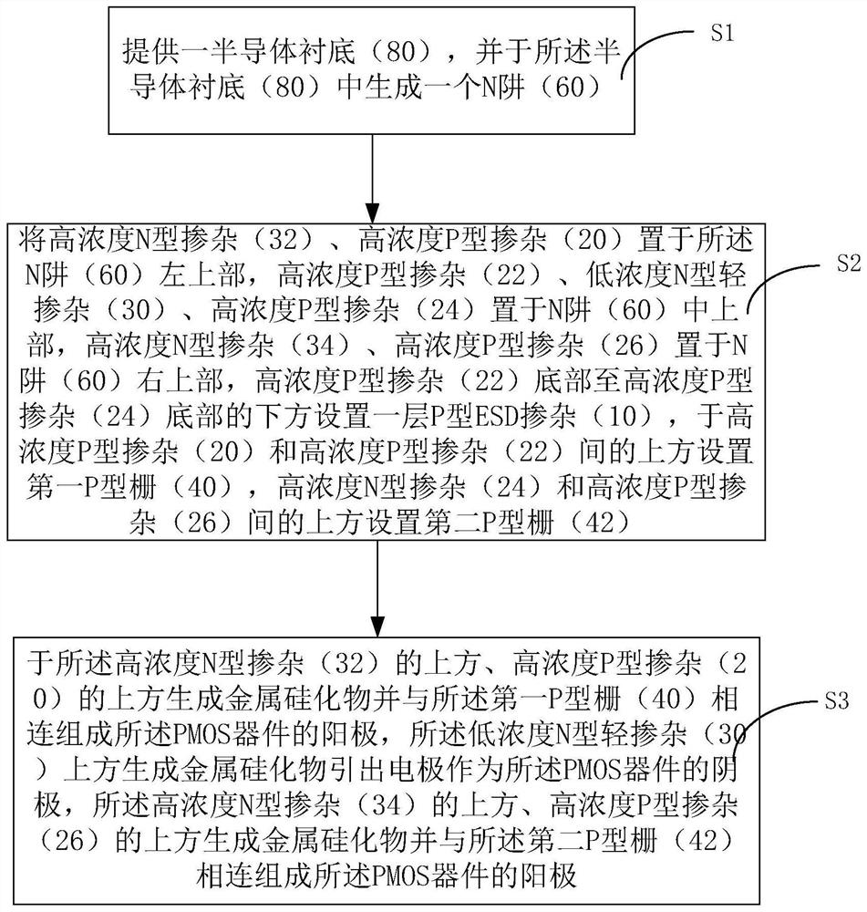
The invention discloses a PMOS device embedded with a silicon-controlled rectifier and a realization method thereof. The high-concentration N-type doping connected to the cathode of the existing PMOS device embedded in a silicon-controlled rectifier is replaced by a low-concentration N-type light doping ( 30), and form a metal silicide on the upper surface of the low-concentration N-type lightly doped (30), and the lead-out electrode is used as the cathode of the PMOS device, while removing the high-concentration P-type doping (20) and the high-concentration P-type The P-type ESD doping below the doping (26), the present invention can improve the secondary breakdown current of the PMOS device and at the same time increase its sustain voltage higher than its working voltage.

Description

technical field [0001] The invention relates to the technical field of semiconductor integrated circuits, in particular to a PMOS device embedded with a silicon-controlled rectifier for ESD (Electro-Static Discharge, electrostatic discharge) and a method for realizing the same. Background technique [0002] In the field of integrated circuit anti-static protection design, the anti-static protection design window generally depends on the operating voltage and the thickness of the gate oxide layer of the internal protected circuit. Taking the industry's conventional 28nm high-K / Metal Gate process platform as an example, the thickness of the gate oxide layer of the IO device is about 40A, and the working voltage is 1.8V. Then the anti-static protection design of the 28nm high-K / Metal Gate process platform The window is usually between 2.2V and 8V. [0003] Due to the relatively low mobility of internal carriers and holes in PMOS devices, the secondary breakdown current It2 of ...

Claims


Application Information

Patent Timeline
Patent Type & Authority Patents(China)
IPC IPC(8): H01L27/02
CPCH01L27/0262
Inventor 朱天志
Owner SHANGHAI HUALI MICROELECTRONICS CORP
Learn More