
A mold for forming variable-section piles

A technology of variable-section piles and molds, applied in molds, ceramic molding machines, mold auxiliary parts, etc., can solve the complex structure of concave-convex prefabricated pile molds, the inconsistency between the arc block and the outer wall of the small diameter section, and the pile body and the small diameter section. The relative friction of the surrounding soil is limited, so as to prevent the deformation of the mold, closely fit the effect, and enhance the anti-pulling bearing performance.

Active Publication Date: 2021-07-16
周兆弟
View PDF4 Cites 0 Cited by
  • Summary
  • Abstract
  • Description
  • Claims
  • Application Information

AI Technical Summary

Problems solved by technology

[0005] Although the above-mentioned concave-convex prefabricated pile mold can be used to make variable-section piles that improve the uplift bearing performance through the concave-convex molded plate, there is a problem of complex structure in the concave-convex precast pile mold; The inner wall of the mold and the lower mold fits together, which makes the outer end surface of the prefabricated reinforcement of the formed prefabricated pile flush with the outer wall surface of the large diameter section of the prefabricated pile. Then, when the prefabricated pile is used, the prefabricated reinforcement separates the surrounding soil into multiple parts. Isolated arc-shaped block, which makes the arc-shaped block and the outer wall of the small-diameter section not tightly fitted, resulting in a limited increase in the relative friction between the pile body and the surrounding soil, thereby improving the uplift bearing performance of the concave-convex prefabricated pile limited

Method used


Image

  • A mold for forming variable-section piles
  • A mold for forming variable-section piles
  • A mold for forming variable-section piles

Examples


Embodiment 1

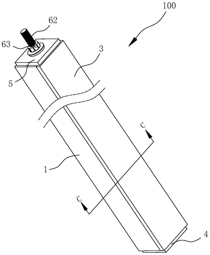
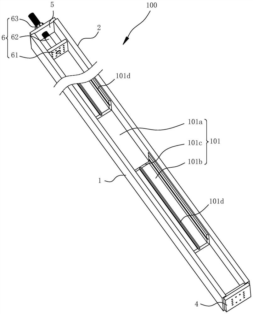
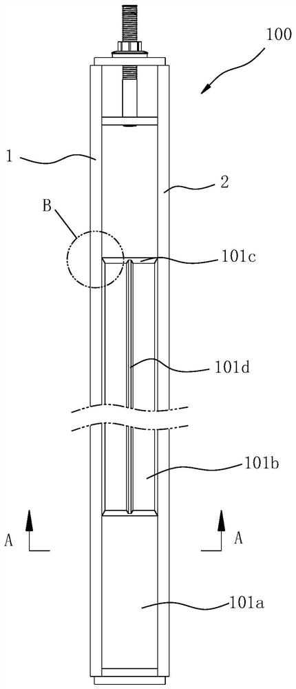
[0057] Such as figure 1 and figure 2 As shown, the present embodiment provides a mold 100 for forming variable-section piles. The mold cavity 101 of the mold 100 forms a plurality of regular polygonal thick-hole sections 101a and a plurality of regular polygonal fine-hole sections 101b along the length direction, each regular polygon The polygonal coarse-pore segments 101a and the regular polygonal fine-pore segments 101b are alternately arranged and communicated with each other. Of course, in the mold provided by the present invention, the mold cavity 101 of the mold forms at least one regular polygonal coarse hole segment 101a and at least one regular polygonal fine hole segment 101b along the length direction, and the regular polygonal coarse hole segment 101a and the regular polygonal fine hole segment 101b Just connect.

[0058] Such as Figure 2 to Figure 5 As shown, a shoulder surface 101c is formed between the hole wall of the regular polygon coarse-hole section 10...

Embodiment 2

[0072] In this embodiment, the parts that are the same as in the first embodiment are given the same reference numerals, and the same text descriptions are omitted.

[0073] Such as Figure 16 As shown, compared with Embodiment 1, the mold 200 for forming variable-section piles provided by this embodiment also has the following structure:

[0074] The hole wall of the regular polygon rough hole section 101a is provided with a plurality of ribs 101k at intervals around the central axis. Specifically, the hole wall of the regular polygon rough hole section 101a is provided with two ribs 101k on each flat surface, and the length of the mold 200 direction, the ribs 101k and the grooves 101d are staggered. Certainly, in the mold provided by the present invention, at least one rib 101k may be provided on the hole wall of each regular polygonal rough hole section 101a, or only part of the regular polygon rough hole section 101a is provided with the rib 101k. It is also possible tha...

Embodiment 3

[0083] In this embodiment, the parts that are the same as in the first embodiment are given the same reference numerals, and the same text descriptions are omitted.

[0084] Such as Figure 22 As shown, compared with the first embodiment, the mold 300 for forming variable-section piles provided by this embodiment also has the following structure:

[0085] The mold 300 for forming variable-section piles at least includes; the first regular polygon coarse hole section 301a, the second regular polygon coarse hole section 301b, the third regular polygon coarse hole section 301c, the first regular polygon fine hole section 302a and the second regular polygonal pore segment 302b.

[0086] Wherein, in the straight line direction from the second end plate 5 to the first end plate 4, the cross-sectional dimensions of the first regular polygon rough hole section 301a, the second regular polygon rough hole section 301b and the third regular polygon rough hole section 301c increase sequ...


PUM


Abstract

The invention discloses a mold for forming variable-section piles. The mold cavity of the mold forms at least one regular polygonal thick hole section and at least one regular polygonal fine hole section along the length direction, and the regular polygonal thick hole section and the regular polygonal thick hole section The regular polygon fine hole section is connected; wherein, the hole wall of the regular polygon fine hole section is provided with at least one groove; the mold is in the cross section of the regular polygon coarse hole section, and the hole wall reaches the mold The shortest linear distance of the central axis is D1; ​​the mold is in the cross-section of the regular polygon fine hole section, the shortest linear distance from the hole wall to the central axis of the mold is D2, and the difference between D1 and D2 is greater than The groove depth of the groove. The mold for forming variable-section piles has the advantage of simple structure, and can meet the requirements of forming variable-section piles with better pullout resistance and bearing performance.

Description

technical field [0001] The invention relates to the field of pipe pile molds, in particular to a mold for forming variable-section piles. Background technique [0002] Under normal circumstances, reinforced concrete prefabricated piles are round piles or square piles prefabricated through molds in the factory, and then transported to the location where the pile is located, and a certain degree of technical measures such as hammering and static pressure are applied to it. On the basis of the application, the pile body enters the predetermined position. Compared with other piles, the reinforced concrete prefabricated pile shows a relatively strong load capacity, relatively small settlement deformation, and good construction performance during the actual application process. It has the advantages of simplicity, low cost and relatively high efficiency, so it has been widely used in pile foundation engineering. Existing concrete prefabricated piles are usually straight piles wit...

Claims


Application Information

Patent Timeline
Patent Type & Authority Patents(China)
IPC IPC(8): B28B7/00B28B23/04
CPCB28B7/0002B28B7/0029B28B23/043
Inventor 周兆弟
Owner 周兆弟
Learn More