
A Fiber Optic Hydrophone Array Structure Based on Compensation Interference

A technology of optical fiber hydrophone and array structure, which is applied to instruments, vibration measurement in fluids, and measurement devices. Tone noise self-suppression, reducing long-distance transmission noise, and achieving stable demodulation effects

Active Publication Date: 2021-08-06
NAT UNIV OF DEFENSE TECH
View PDF10 Cites 0 Cited by
  • Summary
  • Abstract
  • Description
  • Claims
  • Application Information

AI Technical Summary

Problems solved by technology

[0004] (2) In terms of long-distance transmission technology of fiber optic hydrophones, with the increase of the transmission distance of analog optical signals, it is also accompanied by coherent Rayleigh scattering noise (Rayleigh), stimulated Brillouin scattering (stimulated Brillouin scattering, SBS), four-wave The intensification of linear and nonlinear noise such as frequency mixing (Four-Wave Mixing, FWM) affects the weak acoustic signal detection capability of fiber optic hydrophones
[0008] 1. In the equi-arm compensation interference structure using heterodyne demodulation, the round-trip length of the array delay fiber length is equal to the arm difference of the horse-increasing compensation interferometer, that is, the interference delay after compensation Δτ=0, resulting in Δf 2 ×Δτ≡0, unable to satisfy the phase modulation scheme Δf 2 ×Δτ=k (k is a positive integer) requirements
Therefore, the suppression of SBS noise in remote transmission can only be achieved by controlling the optical power injected into the remote fiber below the SBS threshold.
Compared with the phase modulation stimulated Brillouin scattering suppression scheme, the total optical power budget of the system will be reduced by more than 10dB, and the long-distance transmission distance and array scale are greatly limited
[0009] 2. The equi-arm compensation interference structure of heterodyne demodulation introduces a fixed frequency difference Δf into the two beams of interference light field, and extracts signals of related frequencies to demodulate the phase information of the hydrophone. The heterodyne demodulation scheme Does not have the ability to suppress noise
However, the disadvantage of this solution is that each probe of the array is an independent Michelson interferometer, and the number of couplers, optical fibers, mirrors, and fusion points used in the time-division multiplexing array is 2 to 3 times that of the compensation interference structure.
Therefore, in the actual production process of large-scale arrays, the independent probe scheme greatly increases the complexity of the process compared with the compensation interference scheme, and also increases the optical loss and cost of the array, which has obvious disadvantages

Method used


Image

  • A Fiber Optic Hydrophone Array Structure Based on Compensation Interference
  • A Fiber Optic Hydrophone Array Structure Based on Compensation Interference
  • A Fiber Optic Hydrophone Array Structure Based on Compensation Interference

Examples


Embodiment Construction

[0043] The following will clearly and completely describe the technical solutions in the embodiments of the present invention with reference to the accompanying drawings in the embodiments of the present invention. Obviously, the described embodiments are only part of the embodiments of the present invention, not all of them. Based on the embodiments of the present invention, all other embodiments obtained by persons of ordinary skill in the art without creative efforts fall within the protection scope of the present invention.

[0044] It should be noted that all directional indications (such as up, down, left, right, front, back...) in the embodiments of the present invention are only used to explain the relationship between the components in a certain posture (as shown in the accompanying drawings). Relative positional relationship, movement conditions, etc., if the specific posture changes, the directional indication will also change accordingly.

[0045] In addition, in t...


PUM


Abstract

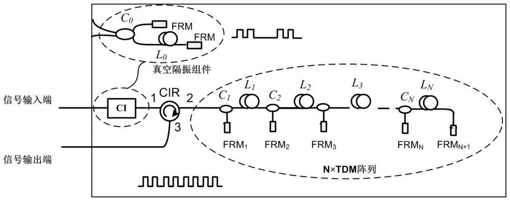
The invention discloses an optical fiber hydrophone array structure based on compensation interference, comprising: a signal input terminal for inputting a pulse signal; a compensation interference component having an unbalanced arm difference for converting the pulse signal into a delayed pulse signal Pair and output; light ring component, used to transmit pulse signal pair; time division multiplexing array component, with time division multiplexing array, used to split and delay pulse signal pair, and obtain each delayed signal after sensing signal Combining beams, and transmitting the time-division multiplexing interference pulse signal with the sensing signal from the input and output ports to the second port of the optical ring component; the signal output terminal is used to output the time-division multiplexing interference pulse signal with the sensing signal . It can greatly improve the comprehensive performance of the long-range transmission array of large-scale optical fiber hydrophones, so that it can meet the application requirements of related fields such as fixed arrays of optical fiber hydrophones on the seabed and shore.

Description

technical field [0001] The invention relates to the technical field of optical fiber hydrophones, in particular to an array structure of optical fiber hydrophones based on compensation interference. Background technique [0002] Optical fiber hydrophone is a fiber optic sensor based on optical fiber and photoelectric technology, which uses sound waves to detect, locate and identify underwater acoustic targets. Optical fiber hydrophones have the advantages of small size and light weight, and can easily form various underwater optical fiber sensing networks, providing an ideal technical approach for solving problems related to marine development strategies such as underwater acoustic detection and oil exploration. Typical applications of fiber optic hydrophones include submarine shore-based fixed arrays, towed arrays, and snorkeling buoys. Among them, shore-based arrays have the advantages of stable formation, long-term continuous duty, and low self-noise away from ships, whic...

Claims


Application Information

Patent Timeline
Patent Type & Authority Patents(China)
IPC IPC(8): G01H9/00G01H3/00
CPCG01H3/00G01H9/004
Inventor 曹春燕徐攀熊水东姚琼唐启永陈伟候庆凯王付印陈虎
Owner NAT UNIV OF DEFENSE TECH
Learn More