
Intelligent interface design method of numerically-controlled machine tool

A technology of CNC machine tool and interface design, applied in software engineering design, calculation, electrical digital data processing, etc., can solve the problems of limiting the wide use of wire saw machines, performing estimation, and unfriendly interface.

Active Publication Date: 2019-12-03
泉州市大鲨鱼机械科技有限公司
View PDF5 Cites 0 Cited by
  • Summary
  • Abstract
  • Description
  • Claims
  • Application Information

AI Technical Summary

Problems solved by technology

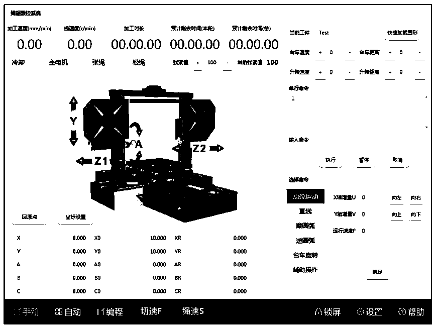
[0003] However, the current interactive interface of the wire saw machine control system has problems such as unfriendly interface, unintuitive operation, and lack of icon-based design. Establish a coordinate system through the operating system (PLC), specify the X-axis and Y-axis directions, and specify the forward and reverse directions. When adjusting the operation, only the parameter value input is displayed on the interactive interface, and the operator needs to be based on the actual moving direction. , corresponding to the coordinate direction specified by the equipment, that is, the operator needs to mark each direction specified by the system, that is, the operator converts the action to the corresponding coordinate system, and judges whether the action direction is positive or negative, forward or reverse, To implement the corresponding parameter adjustment position (such as the positive direction of the X axis) to achieve mechanical control, the interactive interface is only a digital representation during the adjustment process, and the operator cannot intuitively judge the result of the adjustment on the interactive interface, and cannot perform possible The adjustment evolution reference, such an interface design is an artificial barrier, lacks the possibility of intuitive judgment, increases the difficulty of operation, and increases the probability of misoperation; moreover, the functions needed for manual machine adjustment on the current interface are distributed in different submenus Inside, when manually operating, it is necessary to switch back and forth between the main interface and the setting interface frequently. Some necessary parameter designs are not intuitively displayed on the home page of the interface, and it is impossible to intuitively determine whether the parameters have been adjusted completely and whether the parameters are adjusted correctly. Cause setting omission or error
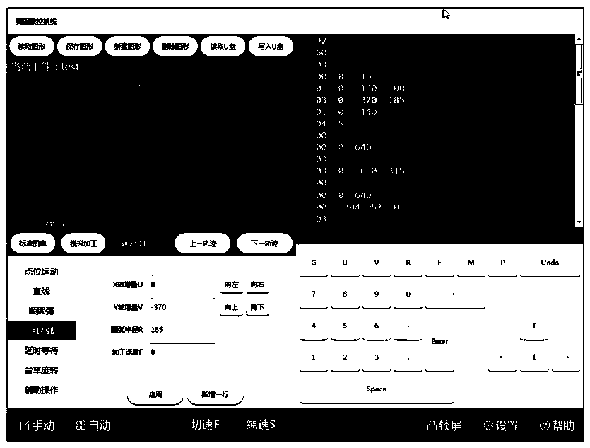
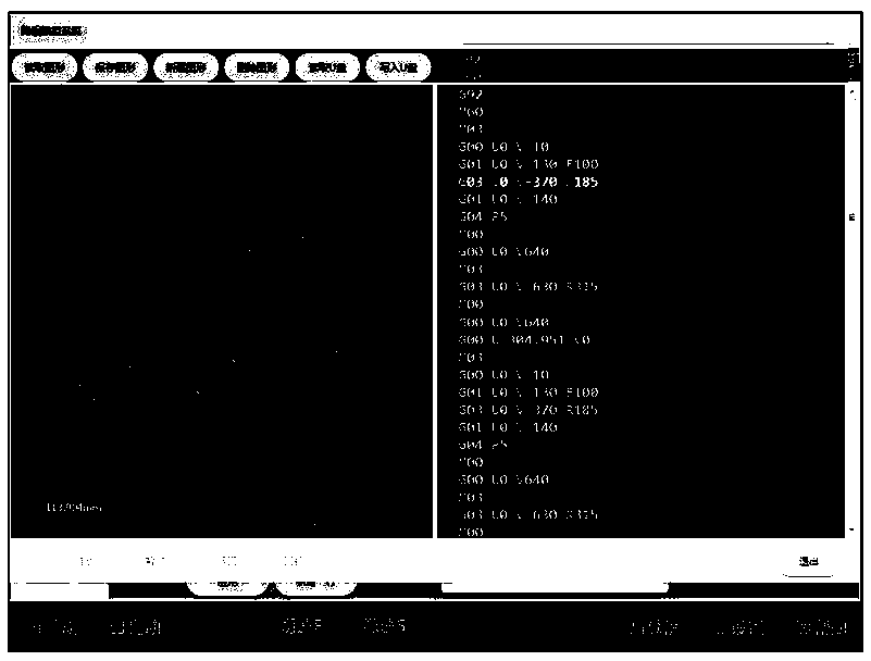
[0004] In addition, the graphic editing interface of the interactive interface of the wire saw machine control system is used to edit the processing graphics to drive the wire saw machine to process the workpiece into various graphics required. However, the interaction of the current wire saw machine control system The editing interface of processing graphics on the interface has problems such as poor human-computer interaction experience, single program input method, complex programming language, no programming prompts or notes, and cumbersome operations. Workers with a professional background first recite professional codes and master programming skills, which makes it difficult for novices to get started and limits the wider use of wire saw machines; at the same time, the system code modification editing interface cannot intuitively reflect the changes before and after modification. In terms of the change of the legend, and the existing editing interface lacks the simulation processing function, it is impossible to predict the execution of the input program, and it is easy to make operation mistakes, and the practicability is low

Method used


Image

  • Intelligent interface design method of numerically-controlled machine tool
  • Intelligent interface design method of numerically-controlled machine tool
  • Intelligent interface design method of numerically-controlled machine tool

Examples


Embodiment Construction

[0029] The present invention will be further described in conjunction with the accompanying drawings and specific embodiments.

[0030] refer to Figure 1 to Figure 4 , the embodiment of the present invention discloses that an intelligent interface design method of a numerical control machine tool is applied to the interface of the controller of the numerical control machine tool, the interface includes a manual operation interface and a graphic editing interface; and programming, click manual to display the manual operation interface, click programming to display the graphic editing interface.

[0031] The manual operation interface is divided into a first functional area and a second functional area from left to right, and the first functional area is distributed from top to bottom with a working status display column, a key component status adjustment area, a jog adjustment area and Coordinate state display area; the second functional area is distributed from top to bottom...


PUM


Abstract

The invention relates to the technical field of wire saw numerical control, and provides an intelligent interface design method of a numerical control machine tool, which comprises the following steps: embedding an action button into a three-dimensional icon in a manual operation interface, and marking an adjustment direction, so that operation is more direct, and errors are prevented; integratingcommon and associated buttons into the same area, so that the operation is smoother and more efficient; adding a key component state information column so that states can be switched and parameters can be adjusted conveniently and quickly; displaying program languages and graphs in the graph editing interface in a combined manner so that editing prompts can be effectively provided for operators.The interface interactivity is high. Editing input methods are diversified. Editing operation is simplified, operation is facilitated, meanwhile, simulation machining can be conducted, execution estimation can be conducted, accidents are eliminated, the effective correctness of editing execution is improved, and misoperation is avoided. The interface distribution configuration which is simple, visual, easy to learn and use, flexible, convenient and fast to operate and capable of freely and flexibly conducting multifunctional operation adjustment is achieved.

Description

technical field [0001] The invention relates to the technical field of numerical control control of a wire saw machine, in particular to an intelligent interface design method of a numerical control machine tool. Background technique [0002] At present, the wire saw machine control system includes a controller with an interactive interface, a PLC control center, a beaded rope drive system, a travel control system, a head turning system, a hydraulic system, a head traverse system, a guide wheel telescopic system, and a beaded rope tension system. Detection and control system; the interactive interface sends various control commands to the PLC control center through RS485 communication. The front and rear displacement and rotation of the trolley), the beaded rope drive system, the head overturning system (controlling the rotation of the left guide wheel and the right guide wheel of the wire saw machine) and the hydraulic system are controlled by the hydraulic system to contro...

Claims


Application Information

Patent Timeline
IPC IPC(8): G06F8/38
CPCG06F8/38
Inventor 傅师铭吴白纯许金灿
Owner 泉州市大鲨鱼机械科技有限公司
Learn More