Motor driving circuit and method thereof

A motor drive and drive circuit technology, applied in the direction of electrical components, electromechanical devices, electronic commutators, etc., can solve the problems of power consumption of brushless DC motors, low efficiency of brushless DC motors, and increase of feedback current, etc., to achieve Effect of reducing feedback current, reducing power, and eliminating offset

Active Publication Date: 2019-12-03
ANPEC ELECTRONICS CORPORATION
View PDF4 Cites 4 Cited by
  • Summary
  • Abstract
  • Description
  • Claims
  • Application Information

AI Technical Summary

Problems solved by technology

[0004] However, in the actual manufacturing process, the placement tolerance of the Hall components will affect the quality of the mass production of the motor. For example, the Hall signal and the driving voltage are in the same phase, but the back electromotive force leads due to the installation tolerance of the Hall components. The drive voltage phase increases the feedback current, which in turn leads to power consumption of the brushless DC motor, making the efficiency of the brushless DC motor lower

Method used


Image

  • Motor driving circuit and method thereof
  • Motor driving circuit and method thereof
  • Motor driving circuit and method thereof

Examples


no. 1 example

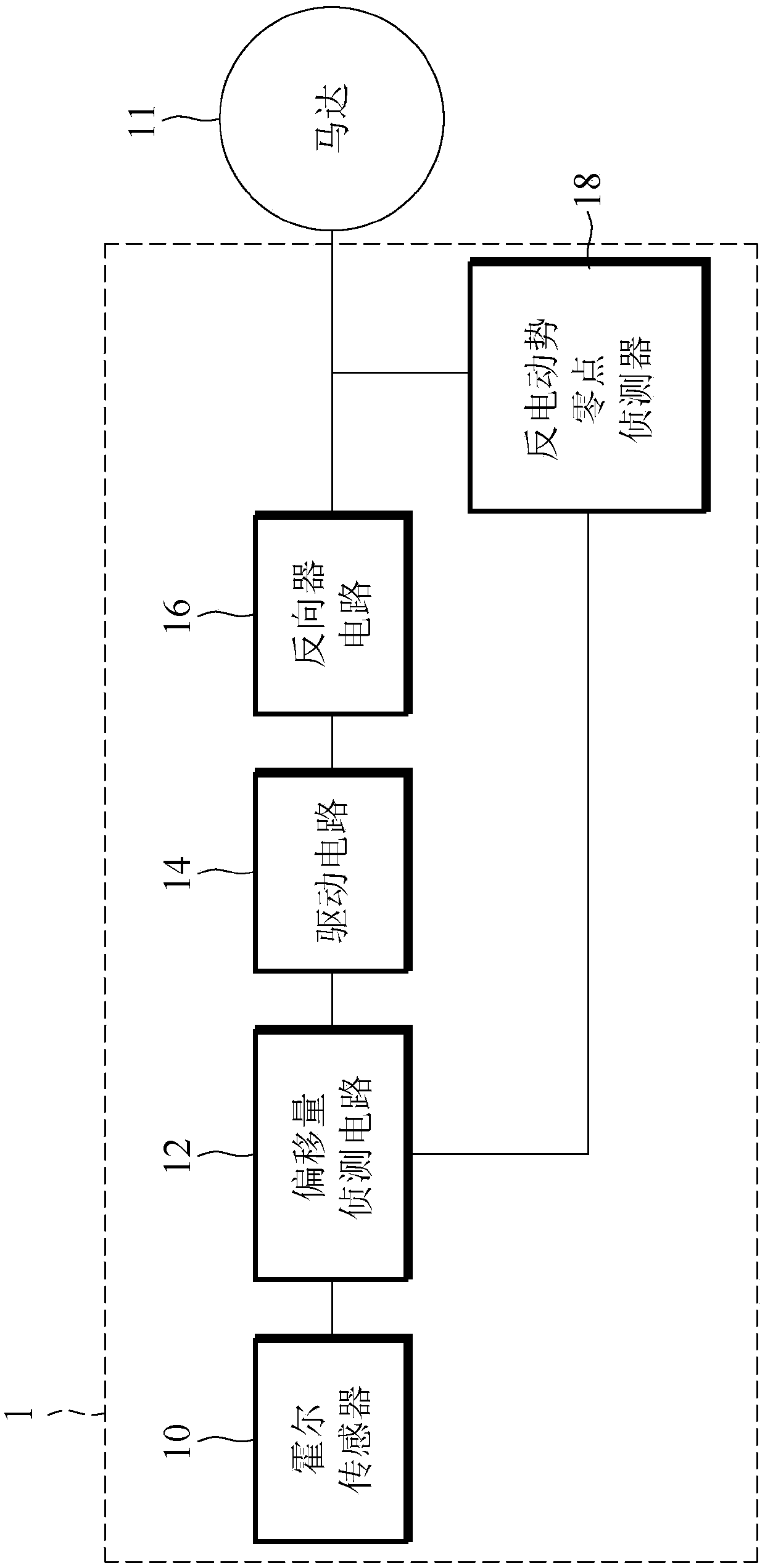
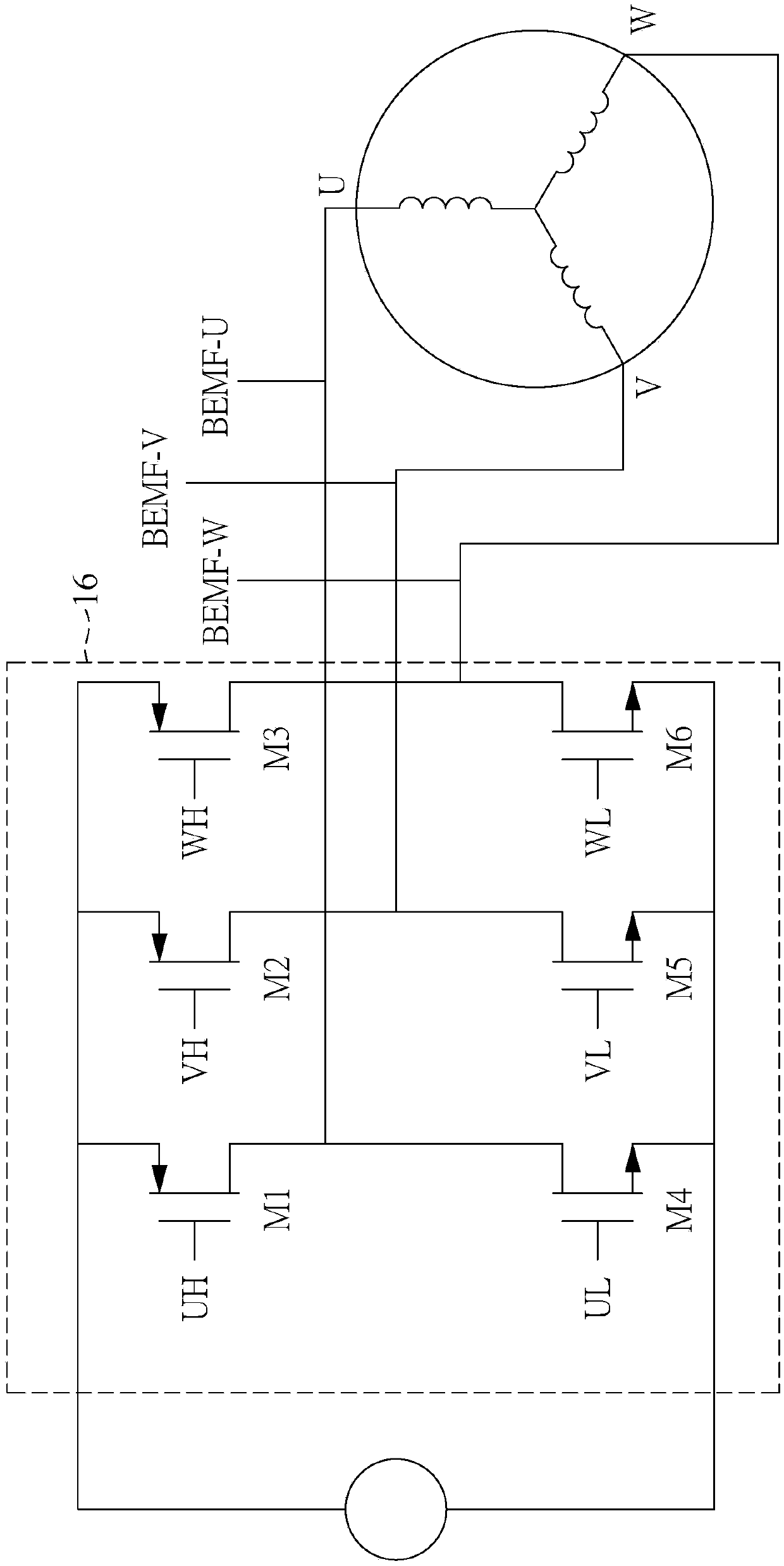
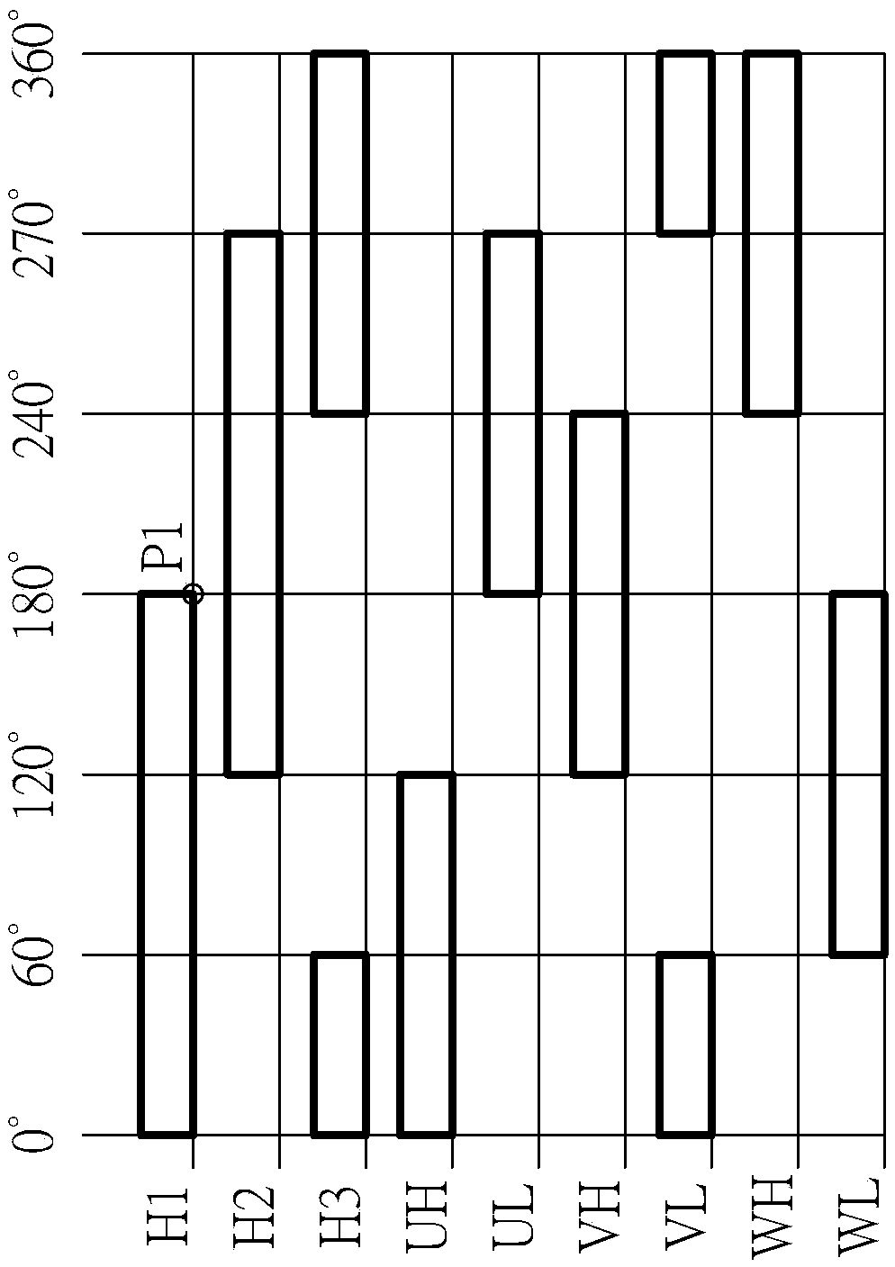
[0028] Please also refer to Figure 1 to Figure 3 , figure 1 It is a circuit structure diagram of the motor driving circuit of the first embodiment of the present invention, figure 2 It is the circuit structure diagram of the three-phase motor and inverter circuit, image 3 Schematic diagram of six-step square wave switching for Hall sensor signal control. refer to figure 1 As shown, the first embodiment of the present invention provides a motor drive circuit 1 for driving a motor 11. The motor drive circuit 1 includes a Hall sensor 10, an offset detection circuit 12, a drive circuit 14, and an inverter circuit. 16 and counter electromotive force zero detector 18.

[0029] The Hall sensor 10 can be arranged adjacent to the motor 11, and is used to sense the change of the magnetic field of the motor 11, and determine the rotor position of the motor 11, so as to generate a Hall signal group accordingly. Taking a three-phase motor as an example, as figure 2 The first Hall ...

no. 2 example

[0051] Please refer to Figure 7 , Figure 7 It is a flow chart of the motor driving method according to the second embodiment of the present invention. The method described in this example can be figure 1 shown in the motor drive circuit 1, so please also follow Figure 1 to Figure 6 To facilitate understanding, the motor driving method includes the following steps:

[0052] Step S100: configure a Hall sensor to detect a rotor position of the motor and generate a Hall signal set. Wherein, depending on whether the motor is a single-phase motor or a three-phase motor, the Hall signal group may have different numbers of Hall signals.

[0053] Step S101: configure the offset detection circuit to receive the Hall signal group and detect the first commutation point of the Hall signal group.

[0054] Step S102: configure the driving circuit to receive the Hall signal group, and generate an initial commutation signal according to the Hall signal group.

[0055] Step S103 : conf...


PUM


Abstract

The invention discloses a motor driving circuit and a method thereof. The motor driving circuit includes a Hall sensor, an offset detecting circuit, a driving circuit and a back EMF zero point detector. The Hall sensor generates a Hall signal group, the offset detecting circuit detects the first phase changing point of the Hall signal group, and the driving circuit generates the initial phase changing signal in the pre-operation mode according to the Hall signal group. In the correction mode, the driving circuit stops outputting the initial phase changing signal, the back EMF zero detector detects the back EMF zero point, and outputs the back EMF zero point signal. The offset detecting circuit detects a phase difference between the first phase changing point and back EMF zero point, and determines a difference value between the phase difference and a predetermined phase difference. Then, the phase of the Hall signal group is adjusted according to the difference value.

Description

technical field [0001] The invention relates to a motor driving circuit and method, in particular to a motor driving circuit and method capable of automatically adjusting the phase of the Hall signal according to the phase difference between the counter electromotive force zero point and the Hall signal to eliminate the offset of the Hall component. Background technique [0002] The biggest feature of the brushless DC motor is the relationship between the brushless structure, and it does not generate noise in principle. This is not only mechanical noise, but also electrical noise. Furthermore, because there are no contact parts, it is easier to manufacture high-speed rotating motors. [0003] When driving a brushless DC motor, the Hall signal output by the Hall component is often used as the starting position of the sine wave. Under ideal conditions, when the Hall component has no installation tolerance, there is no phase difference between the back electromotive force, th...

Claims


Application Information

Patent Timeline
Patent Type & Authority Applications(China)
IPC IPC(8): H02P6/182H02P23/14H02P27/08
CPCH02P6/182H02P23/14H02P27/08H02P6/16H02P6/157H02K29/08
Inventor 杨家泰陈昆民
Owner ANPEC ELECTRONICS CORPORATION
Why Eureka
Try Eureka