
Radioactive source component for gamma knife

A radioactive source and Gamma Knife technology, which is applied in the field of radioactive source components for Gamma Knife, can solve the problems of increased penumbra in the target area, inconvenient disassembly and assembly of radioactive sources, scattered radioactive sources, etc., to reduce the difficulty of shielding , The body structure is highly integrated, and the effect of reducing the layout area

Pending Publication Date: 2019-12-06
成都中核高通同位素股份有限公司
View PDF1 Cites 0 Cited by
  • Summary
  • Abstract
  • Description
  • Claims
  • Application Information

AI Technical Summary

Problems solved by technology

[0003] The shape of the existing gamma knife equipment is spherical or fan-shaped, and the radioactive sources are distributed on it. There are many problems in the distribution of the above-mentioned radioactive sources: 1. Because the panel is too large and the radioactive sources are scattered, the shielding requirements are greater, and there are Risk of radiation source radiation leakage; 2. Because the Gamma Knife equipment is in the shape of a spherical or fan-shaped surface, the γ-rays emitted by some radiation sources are easily blocked by the source hole, resulting in an increase in the penumbra of the target area, resulting in a smaller radiation dose , Insufficient precision, affecting the treatment effect; 3, Disassembly and assembly of radioactive source is extremely inconvenient

Method used


Image

  • Radioactive source component for gamma knife
  • Radioactive source component for gamma knife
  • Radioactive source component for gamma knife

Examples


Embodiment 1

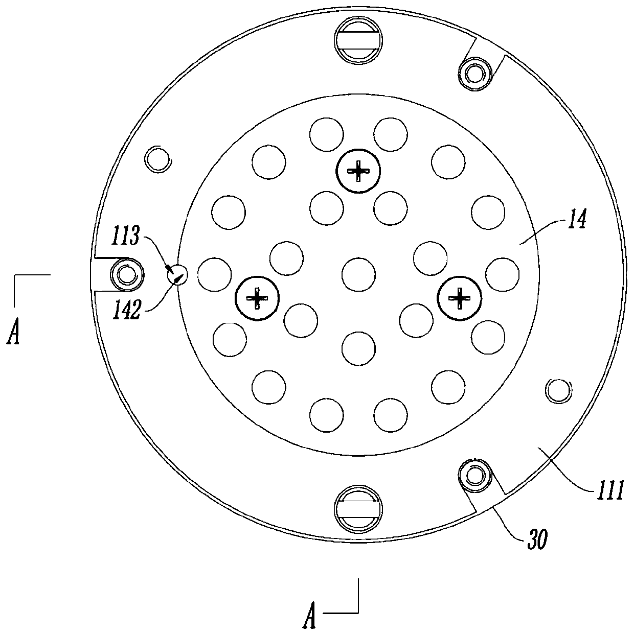
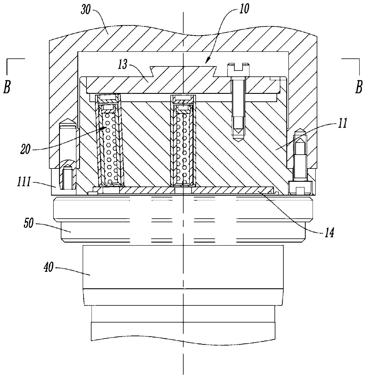
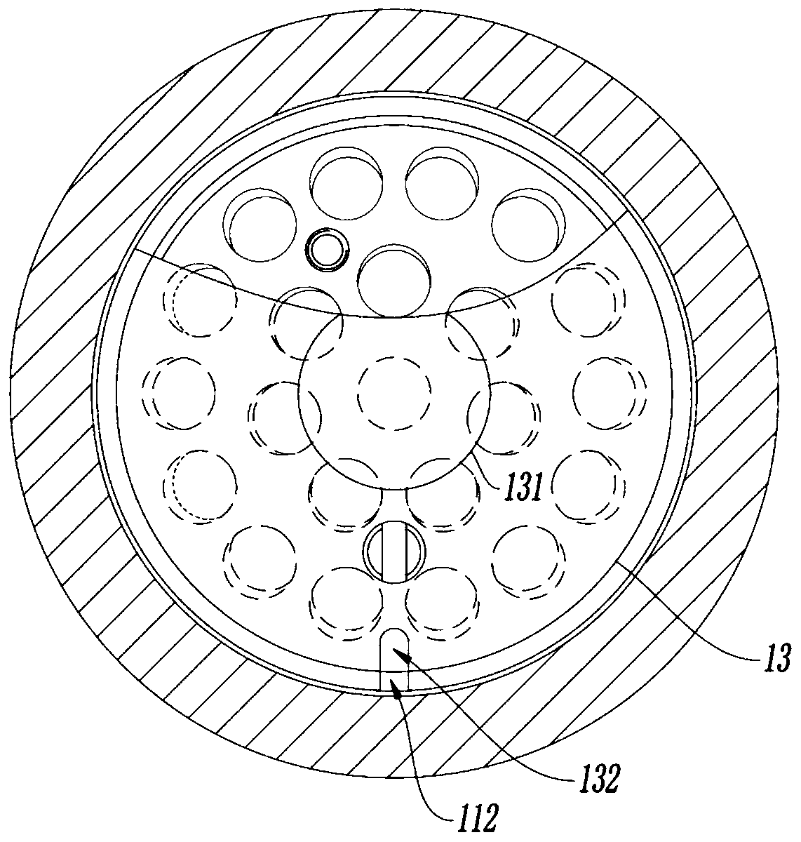
[0044] see Figure 1 to Figure 10 , a radiation source assembly for a gamma knife, including a source box 10 and 22 radiation sources 20 placed in the carrier, gamma rays emitted by the radiation sources 20 can be focused and irradiated on a target point for radiotherapy. The carrier is a source box 10, the source box 10 includes a body 11, and 22 source holes 12 for placing the radioactive source 20 are opened on the body 11; the source hole 12 includes a central source hole 121 and 21 peripheral source holes 122, The central source hole 121 coincides with the central axis of the main body 11, and the peripheral side source holes 122 are arranged around the central source hole 121. The peripheral side source holes 122 are inclined to the central axis of the main body 11, so that the gamma rays emitted by the radiation source 20 can be focused and irradiated on the target point . Preferably improved, the body is cylindrical, of course, the body can also choose other shapes, s...

Embodiment 2

[0054] This embodiment only describes the content different from the foregoing embodiments, and the same content will not be repeated.

[0055] see Figure 7 , a radiation source assembly for a gamma knife, its source box 10 includes 32 source holes 12; the peripheral side source holes 122 are circularly arranged on the side of the central source hole 121, and the peripheral side source holes 122 are two layers, respectively are the source hole 122a on the inner layer and the source hole 122b on the outer layer; the inner layer source hole 122a forms an angle β with the central axis of the body 11, and the outer source hole 122b forms an angle α with the central axis of the body 11 , the angle α is 2.5°, and the angle β is 1.5°. The distance between the focused target point of gamma rays emitted by all radiation sources 20 and the source box 10 is 0.9m.

[0056] The inner diameter of the inner shell 22 is 4.5 mm, the output end (bottom) and the side wall thickness of the inn...

Embodiment 3

[0063] This embodiment only describes the content different from the foregoing embodiments, and the same content will not be repeated.

[0064]A radiation source assembly for a gamma knife, its source box 10 includes 46 source holes 12; the peripheral side source holes 122 are circularly arranged on the side of the central source hole 121, and the peripheral side source holes 122 are two layers, respectively The source hole 122a on the inner layer and the source hole 122b on the outer layer; the inner source hole 122a forms an angle β with the central axis of the body 11, and the outer source hole 122b forms an angle α with the central axis of the body 11, The included angle α is 2°, and the included angle β is 1°; the distance between the focused target point of the gamma rays emitted by the radioactive source 20 and the source box 10 is 0.5m.

[0065] The inner diameter of the inner cladding 22 is 3 mm, the output end (bottom) and the side wall thickness of the inner claddin...


PUM

PropertyMeasurementUnit
The inside diameter ofaaaaaaaaaa
Wall thicknessaaaaaaaaaa
Outer diameteraaaaaaaaaa

Abstract

The invention discloses a radioactive source component for a gamma knife and belongs to the technical field of medical equipment. The radioactive source component comprises a source box and a radioactive source, wherein the source box comprises a body, wherein a plurality of source holes for radioactive source placement are formed in the body; and the source holes include a center source hole andperipheral source holes, the center source hole is superposed with the center axis of the body, and the peripheral source holes are distributed around the center source hole and are tilted to the center axis of the body, so that a gamma ray emitted from the radioactive source can be focused to irradiate a target. The radioactive source component has the beneficial effects that the radioactive source is integrated on the source box, so that the shielding difficulty of a whole machine can be reduced, radiation leakage of the radioactive source can be avoided, and the safety is improved; an emergent beam of the radioactive source has large dosage, the focusing accuracy of the target is high, the penumbra of a target region is reduced, and the radiotherapy effect of a gamma knife is optimized.The radioactive source component is simple and smart in structure and convenient for transferring, assembling and disassembling; and furthermore, the radioactive source can be protected appropriately, the safety is high, and the radioactive source can be assembled and disassembled from the component conveniently.

Description

technical field [0001] The invention relates to the technical field of medical equipment, in particular to a radiation source assembly for a gamma knife. Background technique [0002] Gamma Knife is the main treatment method of stereotactic radiosurgery (Stereotactic Radiosurgery). According to the principle of stereotactic geometry, the diseased tissue is selectively determined as the target, and the γ-ray generated by cobalt-60 is used for one-time treatment. Large-dose focused irradiation can cause focal necrosis or functional changes to achieve the purpose of treating diseases. [0003] The shape of the existing gamma knife equipment is spherical or fan-shaped, and the radioactive sources are distributed on it. There are many problems in the distribution of the above-mentioned radioactive sources: 1. Because the panel is too large and the radioactive sources are scattered, the shielding requirements are greater, and there are Risk of radiation source radiation leakage; ...

Claims


Application Information

Patent Timeline
IPC IPC(8): A61N5/10
CPCA61N5/1042A61N2005/1094A61N2005/1095
Inventor 龙礼国夏冰唐智汤利均张强曹波
Owner 成都中核高通同位素股份有限公司
Learn More