
Integrated circuit chip mounting method and semiconductor device

A technology of integrated circuits and crystal grains, which is applied in the direction of semiconductor devices, semiconductor/solid-state device manufacturing, and electric solid-state devices. efficiency effect

Active Publication Date: 2021-04-30
HOSIN GLOBAL ELECTRONICS CO LTD
View PDF3 Cites 0 Cited by
  • Summary
  • Abstract
  • Description
  • Claims
  • Application Information

AI Technical Summary

Problems solved by technology

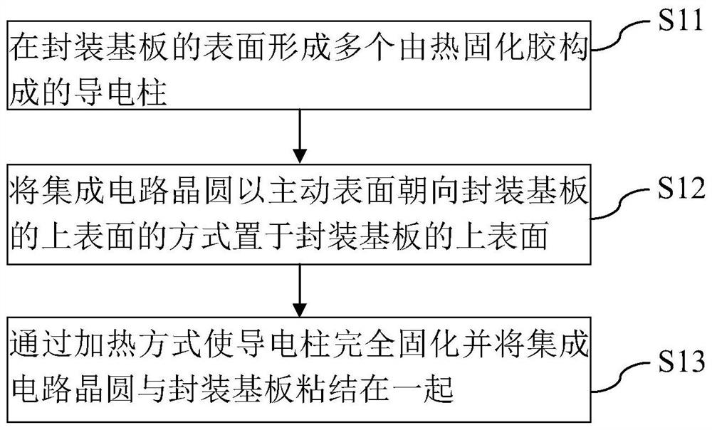
[0005] The technical problem to be solved by the present invention is to provide an integrated circuit die mounting method and a semiconductor device for the problems of long time-consuming patch and wire bonding and high precision requirements in the above-mentioned integrated circuit package.

Method used


Image

  • Integrated circuit chip mounting method and semiconductor device
  • Integrated circuit chip mounting method and semiconductor device
  • Integrated circuit chip mounting method and semiconductor device

Examples


Embodiment Construction

[0029] The following disclosure provides many different embodiments, or examples, for implementing different features of the presented subject matter. Specific examples of components, values, operations, materials, arrangements, etc. are set forth below to simplify embodiments of the invention. Of course, these are examples only and are not intended to be limiting. Other components, values, operations, materials, arrangements, etc. are contemplated. For example, the description below that a first feature is formed "over" or "on" a second feature may include embodiments where the first and second features are formed in direct contact, and may also include embodiments where the first feature is formed in direct contact. Embodiments where an additional feature may be formed between a feature and a second feature such that the first feature may not be in direct contact with the second feature. In addition, the embodiments of the present invention may reuse reference numerals and...


PUM


Abstract

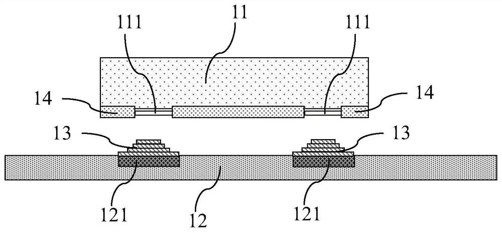
The present invention provides an integrated circuit die mounting method and a semiconductor device. The integrated circuit die mount method includes: forming a plurality of non-conductive wires on the chip pad of the integrated circuit die or on the pins of the packaging substrate. Conductive pillars made of conductive cured adhesive in a fully cured state; placing the integrated circuit die on the upper surface of the packaging substrate with the active surface facing the upper surface of the packaging substrate, and connecting the conductive pillars to the Between the chip pads of the integrated circuit grain and the pins of the packaging substrate; the conductive pillars are completely cured by heating and the integrated circuit grain and the packaging substrate are bonded together, and the integration is realized at the same time Each chip pad of the circuit die is bonded to the corresponding pin of the packaging substrate. The invention can simultaneously realize bonding and fixing between the integrated circuit crystal grain and the packaging substrate and wire bonding, greatly improves the efficiency of the integrated circuit grain packaging, and saves costs.

Description

technical field [0001] The invention relates to the field of integrated circuit packaging, and more specifically, relates to a die mounting method and a semiconductor device. Background technique [0002] Modern products are thin, light and small, so many discrete circuits are integrated into integrated circuits. At present, integrated circuits have been widely used in personal computers, mobile phones, digital cameras, and other electronic devices. In order to provide a stable and reliable working environment for the integrated circuit, and to protect the integrated circuit mechanically or environmentally, so that the integrated circuit can perform normal functions and ensure its high stability and reliability, it is necessary to package the integrated circuit . [0003] Integrated circuit packaging refers to the use of film technology and micro-connection technology to arrange, paste, fix and connect integrated circuits and other elements on the lead frame (Lead Frame) o...

Claims


Application Information

Patent Timeline
Patent Type & Authority Patents(China)
IPC IPC(8): H01L21/60H01L23/498
CPCH01L23/49811H01L24/81H01L2224/818H01L2224/81862
Inventor 赖振楠
Owner HOSIN GLOBAL ELECTRONICS CO LTD
Learn More