Rapid PCR chip and rapid fluorescent quantitative detector

A technology of reaction chip and fluorescence quantification, which is applied to the measurement/inspection of microorganisms, bioreactor/fermenter combination, specific-purpose bioreactor/fermenter, etc., which can solve the problem of slow and inaccurate heating speed and non-concentrated fluorescence reflection , large amount of reaction solution, etc., to achieve the effects of fast heat conduction, accelerated reaction speed, and reduced cost

Pending Publication Date: 2019-12-10
无锡百泰克生物技术有限公司
View PDF1 Cites 5 Cited by
  • Summary
  • Abstract
  • Description
  • Claims
  • Application Information

AI Technical Summary

Problems solved by technology

[0005] The applicant aims to provide a fast PCR reaction chip with a reasonable structure and a fast fluorescence quantitative detector for the shortcomings of the above-mentioned existing production PCR devices, such

Method used


Image

  • Rapid PCR chip and rapid fluorescent quantitative detector
  • Rapid PCR chip and rapid fluorescent quantitative detector
  • Rapid PCR chip and rapid fluorescent quantitative detector

Examples


Embodiment 1

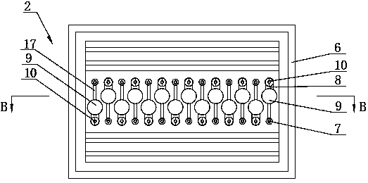
[0032] like image 3As shown, the PCR chip 2 includes a flat cuboid panel 6 and a base film 13 covering the bottom of the entire panel 6. In this embodiment, a number of elongated flow channels with equivalent lengths are provided in parallel along the short side of the rectangle on the bottom surface of the middle part of the panel 6. A circular counterbore reaction tank 9 is set in the middle of the flow channel, and the flow channel and the reaction tank 9 do not penetrate the entire thickness of the panel 6 . like Figure 4 As shown, the bottom film 13 is bonded to the bottom of the panel 6, so that the flow channel and the reaction pool 9 form a closed accommodation space. The reaction pools 9 on the adjacent flow channels are arranged in a staggered manner. On the one hand, more reaction pools 9 can be arranged per unit area, making full use of the limited space of the panel 6. On the other hand, the adjacent reaction pools 9 are far apart to prevent fluorescence Detect...

Embodiment 2

[0042] like Image 6 As shown, in this embodiment, no flow channel is provided, and the sample injection hole 10 and the exhaust hole 7 are directly provided at the opposite ends of the reaction pool 9, which can also realize the purpose of sample injection and exhaust of the reaction solution. After sample injection, A sealing and light-shielding film 14 is attached to the upper surface of the panel 6 to cover the sample injection hole 10 and the exhaust hole 7 .


PUM

PropertyMeasurementUnit
Thicknessaaaaaaaaaa

Abstract

The invention discloses a rapid PCR chip and a rapid fluorescent quantitative detector. The PCR chip comprises a panel and a bottom film, wherein at least one reaction tank is formed in the bottom surface of the panel; the reaction tank does not penetrate through the panel; the two sides of the reaction tank are provided with a sample adding hole and an exhaust hole and communicate with the top surface of the panel; the bottom film is attached to the bottom surface of the panel; and the panel is made of a light-transmitting material. When the PCR chip is arranged on a temperature control module, the bottom film is tightly attached to the temperature control module; a PCR solution in the reaction tank above the bottom film after sample adding is separated from the temperature control moduleby only a layer of bottom film; the refrigerating capacity or the heating capacity of the temperature control module can rapidly penetrate through the bottom film to be conducted to the PCR solution;and compared with a plastic plate, the film is higher in heat conduction speed and more uniform in heat conduction, so that rapid heating or cooling of the PCR solution is realized, and rapid PCR canbe realized. A heating and refrigerating sheet of the rapid fluorescent quantitative detector is horizontally placed; the PCR chip is horizontally placed on the heating and refrigerating sheet; the bottom film is tightly attached to the plane of the heating and refrigerating sheet; and the refrigerating capacity or the heating capacity of the heating and refrigerating sheet can be rapidly and uniformly conducted to the PCR solution.

Description

technical field [0001] The invention relates to the technical field of molecular biology detection, in particular to a fast PCR reaction chip and a fast fluorescence quantitative detector. Background technique [0002] PCR amplification instrument, also known as PCR gene amplification instrument, PCR nucleic acid amplification instrument, polymerase chain reaction nucleic acid amplification instrument, is a kind of amplification instrument for specific DNA using PCR (Polymerase chain reaction, polymerase chain reaction) technology. Instruments and equipment are widely used in medical and biological laboratories, and can be used for the diagnosis of infectious diseases and paternity testing. Based on the three-step principle of PCR reaction, the PCR instrument needs to set three temperature points of denaturation-annealing-extension. In the standard reaction, the double-stranded DNA is denatured at 90~95℃, and then rapidly cooled to 40~60℃, and the primers are annealed. And ...

Claims


Application Information

Patent Timeline
IPC IPC(8): C12M1/34C12M1/38C12M1/00C12Q1/6851
CPCB01L3/5027B01L9/527C12Q1/6851C12Q2563/107C12Q2531/113
Inventor 周志图
Owner 无锡百泰克生物技术有限公司
Why Eureka
Try Eureka