Device and method for uniform pressure electromagnetic forming of sheet metal under the action of different directions of current

A sheet metal and opposite current technology, applied in the field of sheet metal forming, can solve problems such as unbalanced coil force, coil deformation, coil breakage, etc., to reduce deformation or damage, improve forming ability, and improve plasticity Effect

Active Publication Date: 2020-06-23
WUHAN UNIV OF TECH
View PDF1 Cites 0 Cited by
  • Summary
  • Abstract
  • Description
  • Claims
  • Application Information

AI Technical Summary

Problems solved by technology

However, this method has the following disadvantages: First, because the magnitude of the induced current is limited by the coil voltage, it is difficult to generate a strong enough induced current for processing materials with poor conductivity.
This method also has some deficiencies: First, because the electromagnetic force is mutual, the coil is also subjected to the reverse electromagnetic force of a sheet, and this electromagnetic force is only in a single direction of the uniform pressure coil, resulting in The unbalanced force of the coil leads to the deformation of the coil, and the deformation of the coil leads to the change of the magnetic field of the coil, which eventually leads to inconsistent quality and low repeatability of the formed parts produced in the same batch
The bottom of the uniform pressure coil is under the pressure of the plate, and the rest of the coil is under the tension from the bottom, which may easily cause the coil to break

Method used


Image

  • Device and method for uniform pressure electromagnetic forming of sheet metal under the action of different directions of current
  • Device and method for uniform pressure electromagnetic forming of sheet metal under the action of different directions of current
  • Device and method for uniform pressure electromagnetic forming of sheet metal under the action of different directions of current

Examples


Embodiment Construction

[0040] The following is a further description of the sheet metal uniform pressure electromagnetic forming device under the action of different directions of current in conjunction with the accompanying drawings.

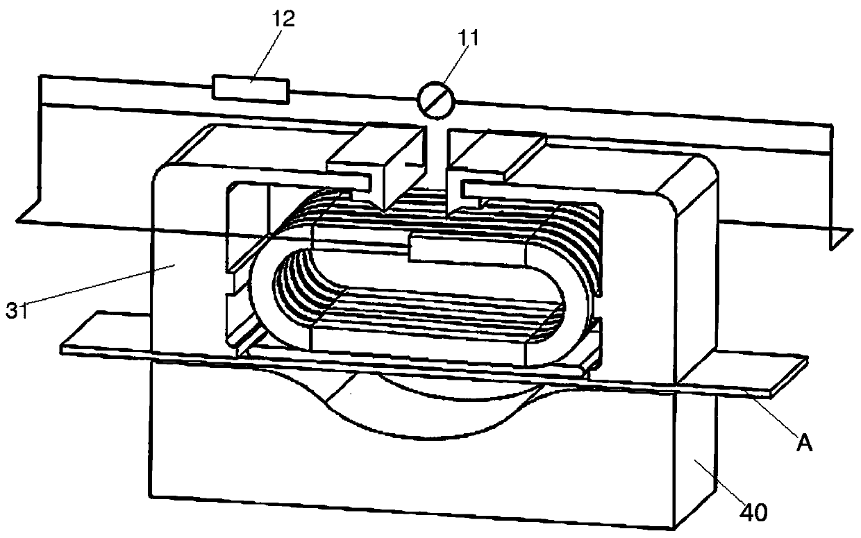
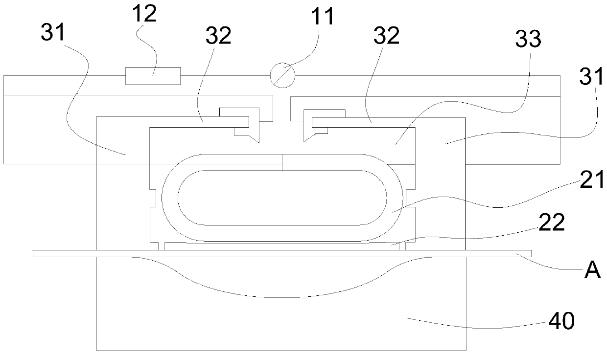
[0041] Such as figure 1 , figure 2 As shown, a metal sheet metal uniform pressure electromagnetic forming device under the action of different directions of current, including a concave mold 40, also includes,

[0042] A capacitive power supply module, which includes an energy storage capacitor 11;

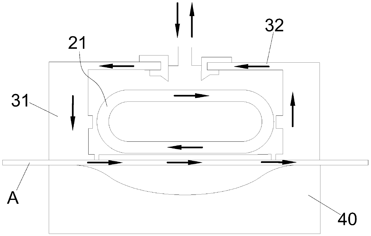
[0043] A magnetic branch circuit, which includes a uniform pressure coil 21, is connected to both ends of the capacitive power supply module;

[0044] Two vertical edge-holding plates 31 have their upper ends bent and extended toward each other to form a closing plate 32, thereby forming a container with an opening facing downward between the two edge-holding plates 31 and below the two closing plates 32. Place the cavity 33, and the uniform pressure coil 21 is fixed...


PUM


Abstract

The invention provides a device for constant-pressure electromagnetic forming of a metal plate under the action of heterodromous currents. The device comprises a u-shaped mold, and further comprises acapacitance power module, a magnet supply branch and two vertical side pressing plates. The capacitance power module comprises an energy storage capacitor. The magnet supply branch comprises a constant-pressure coil and is connected to the two ends of the capacitance power module. The upper ends of the side pressing plates are bent oppositely and extend to form closed plates, and therefore a containing cavity with an opening being downward is formed between the two side pressing plates and below the two closed plates. The constant-pressure coil is fixedly arranged in the containing cavity. During use, a power supply branch is formed by the two closed plates, the two side pressing plates and the to-be-formed metal plate; the power supply branch and the magnet supply branch are connected inparallel and are connected to the two ends of the capacitance power module by taking the free ends of the two closed plates as the electric access points. When the energy storage capacitor carries out discharge, discharge currents opposite in direction are formed in the constant-pressure coil and the power supply branch. According to the device, the magnitude of the currents on the formed plate is enhanced, the stress balance performance of the constant-pressure coil is improved, and processing capacity is improved.

Description

technical field [0001] The invention belongs to the field of sheet metal forming, and in particular relates to a uniform-pressure electromagnetic forming device and method for sheet metal under the action of opposite currents. Background technique [0002] Electromagnetic forming is a high-efficiency forming method. At present, the commonly used forming method is that the external channel is formed by the pressure plate and the sheet material, and the induced current is formed in the external channel through the uniform pressure coil, and then the uniform pressure coil generates electromagnetic force on the generated current, and the sheet material is processed. For this, "Research on Uniform Pressure Coil and Sheet Force in Flat Electromagnetic Forming, Journal of Huazhong University of Science and Technology, Natural Science Edition, Volume 39, No. 2, February 2011". But this method has the following disadvantages: First, because the magnitude of the induced current is li...

Claims


Application Information

Patent Timeline
Patent Type & Authority Patents(China)
IPC IPC(8): B21D26/14
CPCB21D26/14
Inventor 曾小勇刘维周寿露孟正华
Owner WUHAN UNIV OF TECH
Why Eureka
Try Eureka