Welding wheel assembly device for strip steel on-line narrow lap joint seam welding machine

A seam welding machine and strip steel technology, applied in welding equipment, resistance welding equipment, metal processing equipment, etc., can solve problems such as difficulty in observing the use of conductive parts, difficulty in processing and assembling parts, and burnout of taper bushings, etc. , to achieve the effect of easy observation and maintenance, stable and reliable electrical conductivity, and reduced equipment failure rate

Active Publication Date: 2019-12-13
武汉凯奇冶金焊接设备制造有限责任公司
View PDF5 Cites 0 Cited by
  • Summary
  • Abstract
  • Description
  • Claims
  • Application Information

AI Technical Summary

Problems solved by technology

[0007] 1. The structure is too complicated. In the internal structure, the core conductive part (taper sleeve) is installed in the electrode wheel support, which makes the processing and assembly of parts very difficult, and it is difficult to observe the use of the conductive part in production. situation, it is difficult to overhaul;
[0008] 2. When repairing and replacing the internal taper bushing, it is necessary to dismantle the overall structure of the welding wheel assembly. The workload is huge and professional, and it needs a particularly experienced master to complete it. The general fitter master is not competent for this work. Fine and complicated maintenance work has seriously affected the normal operation of the production line;
[0009] 3. The lubricating system and cooling system are integrated in the welding wheel assembly, and the sealing ring is used inside to isolate the two systems. However, in actual use, due to the quality or life of the sealing ring, the lubricating oil often colludes with the cooling water, resulting in unnecessary loss;
[0010] 4. During the initial installation process of the wheel shaft and the taper shaft sleeve, it is necessary to grind and cooperate with each other to make the conductive area as large as possible, so as to avoid the conductive area being too small when the current passes through, and the current passing through the unit area is too large, which will cause severe heat and burn the cone. The shaft sleeve and the axle, but in the actual use process, the conical surfaces that rub against each other will wear out, although the spring on the right side of the cone sleeve will push it tightly to eliminate the gap caused by wear, but the effect is not good;
[0011] 5. Due to the need for good electrical conductivity, the welding wheel assembly uses a large amount of copper materials. For example, the electrode wheel support is made of brass castings, the overall material of the wheel shaft is chrome-zirconium copper, and the material of the taper sleeve is tin bronze. Not only the overall The cost is quite high, which is not conducive to the cost control of the equipment, and also causes the user to purchase the spare parts of the welding wheel assembly very expensively, which increases the burden on the user
[0012] Therefore, the traditional welding wheel assembly is no longer applicable to existing welding equipment in terms of structural rationality and cost control, and it is urgent to develop a new welding wheel assembly to make its structure more reasonable and easy to repair and repair , which can reduce the cost as much as possible and make the overall equipment more competitive

Method used


Image

  • Welding wheel assembly device for strip steel on-line narrow lap joint seam welding machine
  • Welding wheel assembly device for strip steel on-line narrow lap joint seam welding machine
  • Welding wheel assembly device for strip steel on-line narrow lap joint seam welding machine

Examples


Embodiment Construction

[0038] The present invention will be further described in detail below in conjunction with the accompanying drawings and specific embodiments.

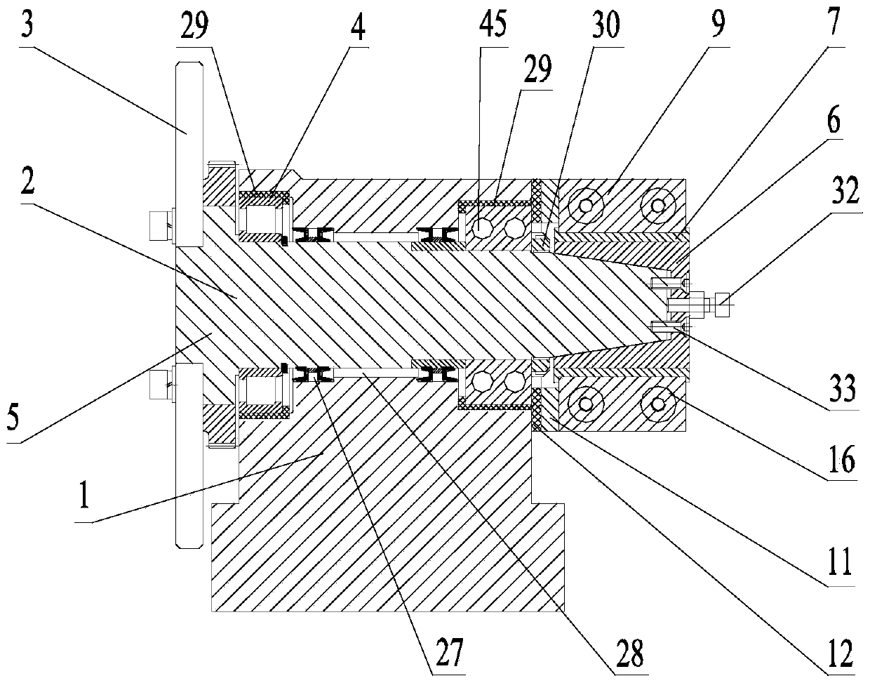
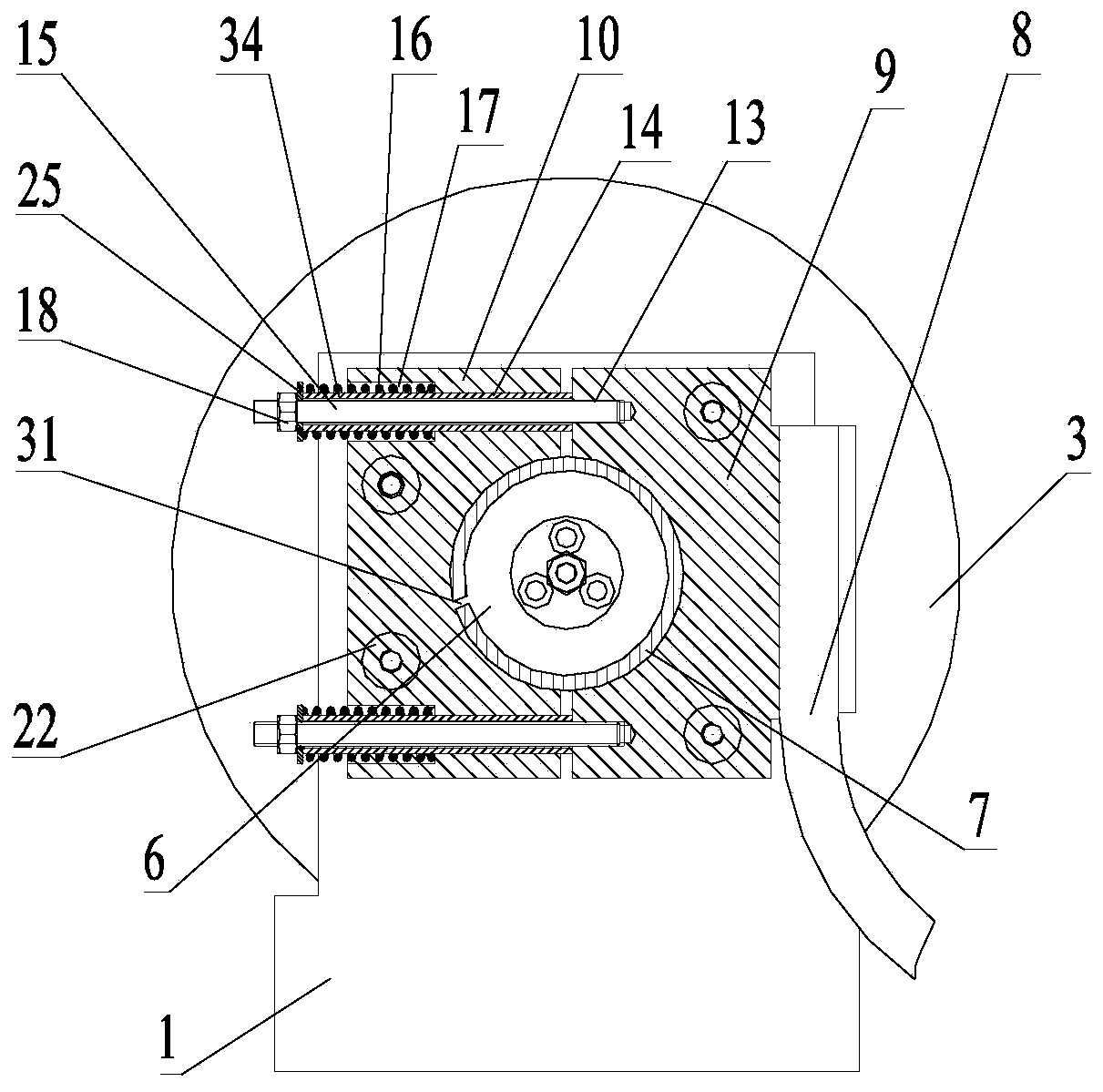
[0039] Such as figure 1 and figure 2 As shown, the welding wheel assembly device of the present invention used for strip steel on-line narrow lap seam welding machine includes an electrode wheel support 1 and an electrode wheel 3 installed on the wheel shaft 2, and the wheel shaft 2 passes through the front bearing arranged at the front end 4 and the rear bearing 45 located at the rear end are installed in the step hole 5 in the horizontal direction of the electrode wheel support 1, the front bearing 4, the rear bearing 45 and the electrode wheel support 1 are all padded with a protective sleeve 29, and the wheel shaft 2 The tail hangs on the outside of the electrode wheel support 1, and the tail of the wheel shaft 2 is fixedly covered with a tapered shaft sleeve 6 through three screws 33. The tail of the wheel shaft 2 is an outer ...


PUM


Abstract

The invention relates to the field of welding, and discloses a welding wheel assembly device for a strip steel on-line narrow lap joint seam welding machine. The welding wheel assembly device comprises an electrode wheel support and an electrode wheel arranged on a wheel shaft, the wheel shaft is arranged in a horizontal stepped hole in the electrode wheel support through a front bearing arrangedat the front end and a rear bearing arranged at the rear end, the tail part of the wheel shaft is suspended on the outer side of the electrode wheel support, and the tail part of the wheel shaft is fixedly sleeved with a conical shaft sleeve through a plurality of screws, the outside of the conical shaft sleeve is a cylinder, a copper sleeve is sleeved outside the conical shaft sleeve, a pressingdevice for tightly pressing the inner cylindrical surface of the copper sleeve and the outer cylindrical surface of the conical shaft sleeve is arranged on the outer side of the copper sleeve, and thepressing device is connected with an electrified copper strip. The welding wheel assembly device for the strip steel on-line narrow lap joint seam welding machine has the advantages that the conductive conical shaft sleeve is partially moved out of the electrode wheel support, the machining and assembly are simple, the production and use are convenient, the production efficiency is remarkably improved, and the equipment cost and the maintenance frequency are reduced.

Description

technical field [0001] The invention relates to the field of welding, in particular to a welding wheel assembly device for an online strip steel narrow lap splicing seam welding machine. Background technique [0002] The welding wheel assembly device is an important part of the narrow lap seam welding machine on the strip steel line. Its function is to transfer the current to the lapped steel strips as completely as possible. Contact resistance, heat will be generated when the current passes through, so that the strip steel will fuse together to realize welding. Therefore, the quality and stability of the welding wheel assembly are related to the normal operation of the whole equipment, and the effect of strip welding is almost all related to it. [0003] In the prior art, the welding wheel assembly device of the narrow lap seam welding machine includes an upper welding wheel assembly and a lower welding wheel assembly, the lower welding wheel assembly is installed at the b...

Claims


Application Information

Patent Timeline
Patent Type & Authority Applications(China)
IPC IPC(8): B23K11/36
CPCB23K11/36
Inventor 芦洪波桂敏敏张同德徐剑张彦李礼陈俊邱磊彭波王卫强张国鸿芦立楷
Owner 武汉凯奇冶金焊接设备制造有限责任公司
Why Eureka
Try Eureka